background image

52

7


Settings and Operations Related to Hold

52

Se
tting

s an
d Op

er

ations Related

 to

 Hold

Chapter

7

7-1.

Hold mode

F325 has a peak hold function that maintains and displays a peak value (maximum value) of input
signals and a sample hold function that maintains and displays an arbitrary point. 
When hold fix section is set as 1: ON, detection section and fix section can be distinguished. 

* Peak hold can be switched between analog and digital. 

Refer to P.59 “7-2.Peak hold selection”.

* Hold value display renewal timing can be changed. 

Refer to P.60 “7-4.Renewal timing of hold value”.

* Prohibition time for preventing chattering of HOLD signals can be set. 

Refer to P.61 “7-5.Hold detection wait”.

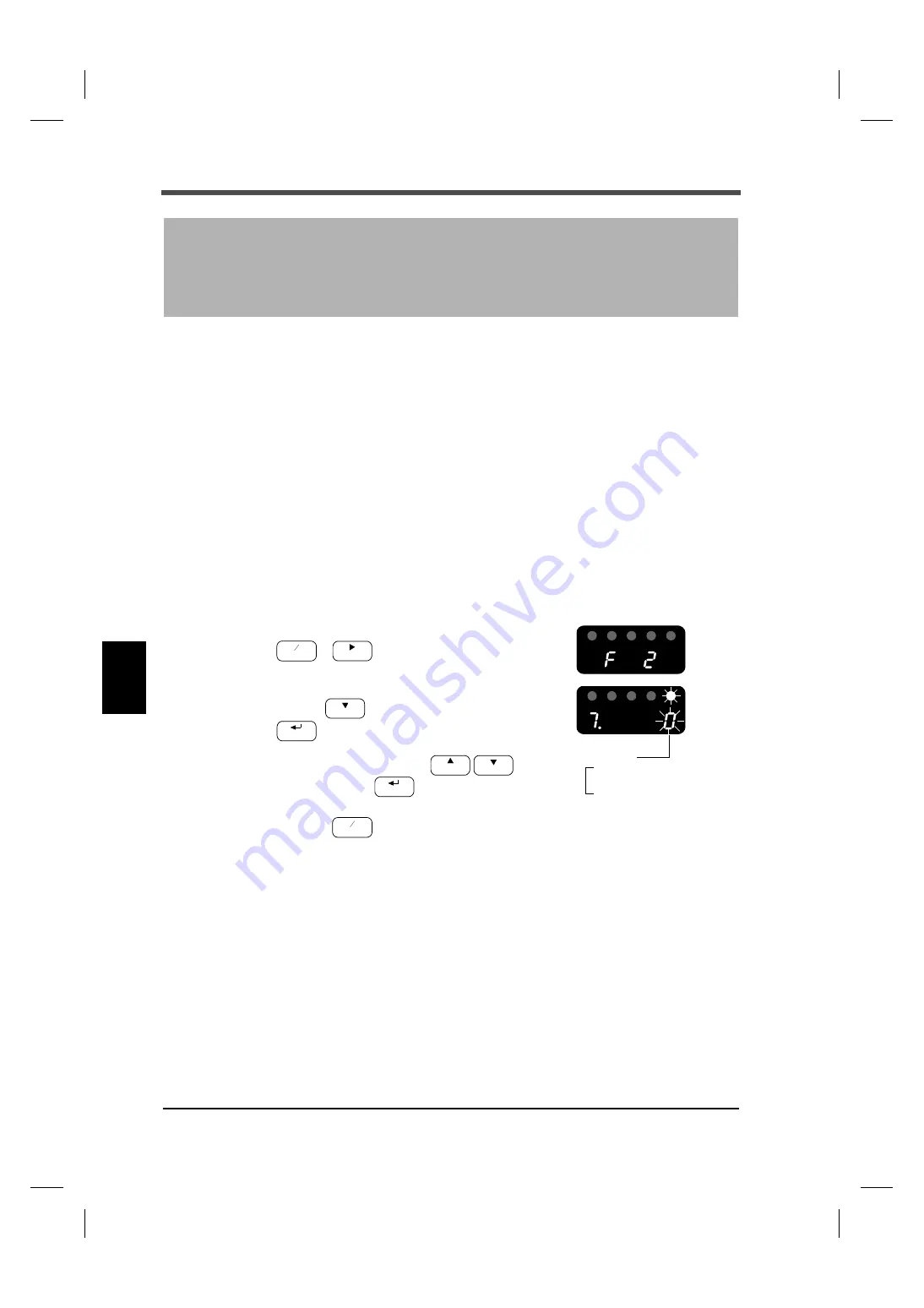
Hold mode setting method

1.

Select setting mode 2.

2.

Select "hold mode".

Press the 

 key seven times.

Set the hold mode using the 

 keys, and

confirm it with the 

 key.

3.

Press the 

 key to return to the indicated value display.

7

Settings and Operations 

Related to Hold

FNC


ZERO

1: Peak hold

0: Sample hold

Hold mode

CAL

HOLD

GAIN

CAL

HOLD

FNC


Summary of Contents for F325

Page 1: ...01JUN2015REV 1 01 DIGITAL INDICATOR F325 OPERATION MANUAL...

Page 2: ...fely Use this indicator with accurate understanding of the contents Keep this operation manual in a safe place to be used for further reference Safety precautions Make sure that installation maintenan...

Page 3: ...re to check that the power is off before the following actions Removal and installation of optional connectors and so forth Wiring and connection of cables to a signal I O terminal Connection to prote...

Page 4: ...arge current surge etc Perform wiring of cables separately from these power lines Do not perform parallel wiring and identical wiring Do not use the indicator if damaged Tighten signal I O terminal sc...

Page 5: ...the F325 package is designed to absorb shock sufficiently during shipping re use of the same packaging materials may damage the indicator when shock is encountered When sending this product to us for...

Page 6: ...fects on the environment and human body RoHS directive RoHS stands for Restriction on Hazardous Substances This is an EU regulation regarding toxic substances This Directive prohibits the use of six s...

Page 7: ...ard not specified at the time of order 14 2 6 SI F Connection RS 485 or SI F specified at the time of order SIF 15 2 7 External output connection 16 2 8 External input connection 17 2 9 Power input te...

Page 8: ...ethod 37 5 4 Sampling rate 37 Sampling rate setting method 37 5 5 Digital low pass filter 38 Digital low pass filter setting method 38 5 6 Motion detect 39 Motion detect setting method 40 5 7 Zero tra...

Page 9: ...ewal timing of hold value setting method 60 7 5 Hold detection wait 61 Hold detection wait setting method 61 7 6 HOLD key valid invalid 62 HOLD key valid invalid setting method 62 8 Settings and Opera...

Page 10: ...IF 107 Connection of SI F 107 Regarding indicated values transmitted by SI F 107 13Options 108 13 1 BCD data output 108 Setting values related to BCD data input 109 Sink type BCO option 110 Source typ...

Page 11: ...Setting section 135 External I O signal 136 Interface 137 Options 138 General performance 140 Accessories 140 15 2 Dimensions 141 Standard 141 When BCO BSC option is selected 142 When DAV DAI option...

Page 12: ...tor Connector for BCD output Included only in AC specifications AC input cord One unit One copy One piece One piece included only in RS 485 specifications One set BCO and BSC output option is selected...

Page 13: ...ut condition is met Flashes HH limit output condition is met Flash is prioritized HI limit output condition and HH limit output condition are subject to change depending on setting values of HI LO lim...

Page 14: ...lay a dot illuminates during NOV RAM writing 3 Error message display Refer to P 133 14 Error Message Display 3 Setting keys These keys are for commands of various settings and operations When indicate...

Page 15: ...ey selects a setting mode and the flashing digit of a setting value When indicated values are displayed This key is used for hold function operation Operations change depending on setting values of ho...

Page 16: ...M4x8 tooth captive washer for installing the main unit 2 Options space One of the following options can be selected BCD parallel data output sink type BCO BCD parallel data output source type BSC D A...

Page 17: ...utputs OK signals 1 This is a PhotoMOS relay output normally open contact A4 LO This outputs LO signals 1 This is a PhotoMOS relay output normally open contact A5 OUT1 This output is used for selectin...

Page 18: ...N from a condition where hold is fixed hold is released once and it returns to the current value and detection status A10 COM This is a common terminal common within input signals of input signals LOA...

Page 19: ...SI F terminal of the counterpart device to be connected no polarity B9 SI F Connect with a SI F terminal of the counterpart device to be connected no polarity B10 SG Not used 1 4 Operating procedures...

Page 20: ...in assignment numbers and to wire cables properly before connecting to the signal I O terminal Make sure that overvoltage applied to the signal I O terminal does not exceed the value specified in cate...

Page 21: ...o the control panel 1 Create holes on the panel in accordance with the panel cutout size 2 Remove guide rails on both sides 3 Fit the F325 in from the front of the panel 4 Install the guide rails from...

Page 22: ...mended tightening torque value is 0 17 to 0 21N m The terminal block is removable Loosen the screws two points pull the terminal block strongly and remove it from the main F325 unit If difficult to re...

Page 23: ...t circuit EXC and S and EXC and S respectively if connecting six wire strain gauge type sensors Cable colors of sensors Cable colors of sensors may differ from one manufacturer to another it may even...

Page 24: ...rox 2V per 1mV V of sensor input Caution The VOL OUT terminal is not insulated from the internal circuit Use shielded cables for connection with external devices and wire the cables within 2 to 3m Do...

Page 25: ...ad end SG terminal B10 terminal is a ground terminal which protects a circuit used on the circuit SG terminal is not normally required to use if the main unit of the F325 and connection counterpart de...

Page 26: ...devices can be connected with no polarity Use two core parallel cables captire cables electric wires with thick coating for construction and so on for wires In case two core parallel cables and captir...

Page 27: ...valent circuit Minus common connection Equivalent circuit Output Spark killer Load Inside F325 Spark killer DC power Varistor Load AC power Vext Output data PhotoMOS relay OFF OFF ON ON PhotoMOS relay...

Page 28: ...tween input terminals A7 to A9 and common terminal A10 Plus common connections and minus common connections are possible Minus common connection of no voltage contact input type standard NVI Equivalen...

Page 29: ...couplers and so on Ic approx Input Input F325 Plus common connection A7 to A9 A10 DC Push Toggle switch switch Relay contact 12 to 24V 10mA common Ic approx Input Input F325 Plus common connection A7...

Page 30: ...g terminals into screw holes and secure them with screws L Black N White Protective grounding Green 5 Attach the terminal block cover Caution An external element must be an element in which Ic 20mA or...

Page 31: ...rs of the same rated current Selecting breakers based only on the stationary rated currents will not lead to a selection of appropriate breakers Consult with breaker manufacturers showing them the abo...

Page 32: ...power is off 2 Remove the terminal block cover 3 Remove the power input terminal block screws two points and protective grounding 4 Fit crimping terminals into screw holes and secure them with screws...

Page 33: ...nd series even for breakers of the same rated current Selecting breakers based only on the stationary rated currents will not lead to a selection of appropriate breakers Consult with breaker manufactu...

Page 34: ...htning surge immunity in the EMC Directives Connection F325 Lightning surge protector PT BE FM and PT 2 PE S 24AC ST are registered trademarks of PHOENIX CONTACT PT BE FM PT 2 PE S 24AC ST DIN rail mo...

Page 35: ...P 66 P 35 P 43 P 62 P 32 P 36 Decimal place P 32 ZERO Set value LOCK ZERO key valid Invalid HOLD key valid Invalid P 31 Setting mode 4 P 78 P 78 P 87 P 109 P 121 P 121 D A output mode P 122 D A zero s...

Page 36: ...GAIN ZERO Alarm HI limit Alarm LO limit Output selection Sampling rate Hold detection wait Renewal timing of hold value P 60 Digital low pass filter Peak hold selection P 60 Hold fix section P 70 BCD...

Page 37: ...n 6 Display frequency 7 Decimal place 8 Excitation voltage Mode 4 1 RS 485 I F setting 2 RS 485 ID 3 RS 485 transmission delay time Flashes Off Status display LED On HI OK HOLD PEAK LO HI OK HOLD PEAK...

Page 38: ...Mode 7 1 I O input check 2 I O output check 3 BCD input check 4 BCD output check 5 RS 232C check 6 RS 485 check 7 Interface 8 Option type 9 Version HI OK HOLD PEAK LO HI OK HOLD PEAK LO HI OK HOLD PE...

Page 39: ...layed Press the key to affix a sign to HI limit LO limit digital offset HH limit LL limit D A zero setting D A full scale setting alarm HI limit and alarm LO limit FNC setting value input is displayed...

Page 40: ...sensor is input using the keys This method does not involve actual load Calibration can be easily performed even when actual load cannot be applied For example the gain is automatically determined by...

Page 41: ...t the minimum value of the digital change desired Omit if there is no change Create an unloaded condition where no force is applied to a sensor and set a zero point of a strain gauge type sensor Apply...

Page 42: ...voltage setting method 1 Select setting mode 3 twice 2 Select excitation voltage Press the key eight times Set the excitation voltage using the keys and confirm it with the key 3 Press the key to retu...

Page 43: ...value display 4 7 Min scale division setting Omit if there is no change The minimum value of digital change is set Min scale division setting method 1 Select setting mode 3 twice 2 Set min scale divi...

Page 44: ...ecomes the actual load value actual load calibration is complete ZERO HOLD Value of the actual load 00001 to 99999 GAIN HOLD GAIN CAL ZERO HOLD In case a calibration error is displayed perform counter...

Page 45: ...Check that a sensor is in an unloaded condition and press the keys As soon as an indicated value becomes zero equivalent input calibration is complete Rated output value 0 050 to 9 999mV V e g Rated...

Page 46: ...libration LOCK to ON 1 using the keys and confirm it with the key 3 Press the key to return to the indicated value display FNC ZERO Calibration LOCK 1 ON 0 OFF CAL HOLD GAIN CAL HOLD FNC Refer to P 14...

Page 47: ...ry noise A cut off frequency of a low pass filter can be selected between 10Hz and 30kHz This filter suppresses frequency components higher than the set frequency The higher the cut off frequency the...

Page 48: ...filter Press the key once Set the moving average filter using the numerical value input and shift keys and confirm it with the key 3 Press the key to return to the indicated value display 5 4 Sampling...

Page 49: ...elect digital low pass filter Press the key five times Set the digital low pass filter using the numerical value input and shift keys and confirm it with the key 3 Press the key to return to the indic...

Page 50: ...ving average filter in operation mode The number of times will change according to the sampling rate Setting sample Motion detect time 0 8 sec Motion detect range 10 scales min scale unit When dn set...

Page 51: ...put and shift keys and confirm it with the key 4 Press the key to return to the indicated value display 5 7 Zero tracking This function tracks automatically slow changes of zero points by drifts and s...

Page 52: ...0 1 to 9 9 sec and the band track ing band in the range of 01 to 99 Also when the time is set to 0 0 sec and the band is set to 00 zero tracking does not work Key points DELAY Indicated value COUNT CO...

Page 53: ...al zero functions DZ response turns ON and if DZ input is turned OFF DZ response turns OFF DZ response is output if DZ response is set to output selection 1 or output selection 2 ZERO OFF ON Sampling...

Page 54: ...hod 1 Select setting mode 1 2 Set digital offset Press the key five times Set the digital offset using the numerical value input and shift keys and confirm it with the key Press the key to insert a mi...

Page 55: ...ak hold selection 1 analog hold mode 1 peak hold RUN Use this function to monitor abnormal conditions Refer to P 75 11 RUN Output for details Hold Use this function to obtain synchronization of hold a...

Page 56: ...alue When HI HH output LO and LL output are all OFF OK output is turned ON HH output and LL output are output if HH limit and LL limit are set in output selection 1 and output selection 2 Decision out...

Page 57: ...e using the numerical value input and shift keys and confirm it with the key Press the key to insert a minus sign 3 Set LO limit Press the key once Set the LO limit value using the numerical value inp...

Page 58: ...e This function specifies the comparison timing Ongoing comparison ALL HI LO limit comparison is continuously performed Comparison at the time of stability MD HI LO limit comparison is performed when...

Page 59: ...limit setting value This function is effective for chattering prevention when signals fluctuate vibrate subtly Comparison conditions HI limit ON condition Indicated value HI limit setting value OFF c...

Page 60: ...lue display Indicated value HI limit HI output LO output Time LO limit 0 Hysteresis range Hysteresis range HI LED LO LED OFF ON OFF ON HI HI HI LO LO LO OK OK OK OK OK HI OFF HI ON With hysteresis Wit...

Page 61: ...alues if used in analog peak hold peak hold selection 1 analog hold mode 1 peak hold but is monitored against indicated values hold values during hold 2 Alarm output is output if an alarm is set to ou...

Page 62: ...r zero using the numerical value input and shift keys and confirm it with the key 3 Press the key to return to the indicated value display t1 t1 Approx 1mS HI OFF ON Overload OFF ON Hold value Alarm H...

Page 63: ...tched between analog and digital Refer to P 59 7 2 Peak hold selection Hold value display renewal timing can be changed Refer to P 60 7 4 Renewal timing of hold value Prohibition time for preventing c...

Page 64: ...ion 2 HOLD input Input Time Sensor input value Indicated value Peak hold section HOLD LED Off On Peak detection hold Peak hold reset PEAK LED Off Off Flashing Off HOLD Off On Peak hold section OFF ON...

Page 65: ...ired for releasing a hold When hold fix section is 1 ON Operation of peak hold Hold output is performed if a hold is set to output selection 1 or output selection 2 HOLD input Time Sensor input value...

Page 66: ...en hold is turned ON with external signals turn it OFF with external signals When hold is turned ON with key inputs turn it OFF with key inputs Refer to P 17 2 8 External input connection for details...

Page 67: ...alue returns to tracking t5 Minimum reset signal range required for releasing a hold Sample hold maintaining arbitrary points When hold fix section is 0 OFF Operation of sample hold Hold output is per...

Page 68: ...ue returns to tracking t3 Minimum reset signal range required for releasing a hold When hold fix section is 1 ON Sample hold operation Hold output is performed if a hold is set to output selection 1 o...

Page 69: ...t selection 2 When hold is turned ON with external signals turn it OFF with external signals When hold is turned ON with key inputs turn it OFF with key inputs Refer to P 17 2 8 External input connect...

Page 70: ...If peak hold is performed in analog higher speed peak can be captured since it is not affected by the sampling rate and so forth However the effects of the moving average filter and digital low pass...

Page 71: ...value is canceled at detection start and an indicated value is returned to the current value display Indicated values are held once hold conditions are met At detection stop The previous hold value is...

Page 72: ...times 2 Select hold detection wait Press the key eight times Set the hold detection wait using the numerical value input and shift keys and confirm it with the key 3 Press the key to return to the ind...

Page 73: ...ng the keys and confirm it with the key 3 Press the key to return to the indicated value display Hold point moves Hold point to be Hold t Tracking Tracking Since input is not recognized Hold section t...

Page 74: ...dicated values can also be held for three seconds indicated value hold function Indicated value hold function operations 8 Settings and Operations Related to SI F Print Indicated value Stable OFF ON N...

Page 75: ...the key six times Set the automatic printing using the keys and confirm it with the key 3 Press the key to return to the indicated value display Indicated value Stable OFF ON Near zero OFF ON Time Ne...

Page 76: ...hold fix Hold value printing setting method 1 Select setting mode 6 five times 2 Select hold value printing Press the key seven times Set the hold value printing using the keys and confirm it with th...

Page 77: ...LOCK setting method 1 Select setting mode 3 twice 2 Select set value LOCK Press the key once Switch the set value LOCK to ON 1 using the keys and confirm it with the key 3 Press the key to return to...

Page 78: ...ues Password setting method 1 Select setting mode 4 three times 2 Set password Press the key eight times Set the password using the numerical value input and shift keys and confirm it with the key Ini...

Page 79: ...supply ON while pressing the key Self check completes in approx 30 seconds The memory condition of the F325 is considered normal if and an indicated value are displayed at the end Caution If is not d...

Page 80: ...ritten to the factory default values Initialization setting method 1 Turn OFF the F325 power supply 2 Turn the power supply ON while pressing the key and the key Initialization is performed after self...

Page 81: ...ed even if the setting mode is switched A stationary output condition returns after all are completed 9 6 BCD input check The current condition of BCD input is displayed In BCD input check display the...

Page 82: ...x 1 6 sec All outputs ON All outputs OFF All outputs OFF Only A2 1 output ON Approx 0 8 sec Approx 0 8 sec Only A3 2 output ON Only A5 8 output ON Only A4 4 output ON Approx 0 8 sec Only B13 STROBE ou...

Page 83: ...d value display even without key operation 9 9 RS 485 check Checking of receiving data of RS 485 and compulsory transmitting of data are implemented When implementing the check set the mode of RS 485...

Page 84: ...RS 485 or SI F 9 11 Option type A condition of option installation is displayed optional slot 9 12 Version A version is displayed Interface 485 RS 485 SIF SI F Option type non BCO dAV dAI 232 BSC BCD...

Page 85: ...Example of connecting output equivalent circuit and external device The output voltage is not an indicated value since it is retrieved from the front stage where sensor input signals are A D converted...

Page 86: ...F operation are output to check if CPU is operating properly If ON or OFF for a few seconds consider it as an error RUN output specification RUN output is performed if a RUN is set to output selection...

Page 87: ...tions Message format Modbus RTU UNI Format Signal level Based on RS 485 Two wire Transmitting distance Approx 1 km Transmitting method Asynchronous half duplex Transmitting speed Selectable from 1200...

Page 88: ...nit of the F325 and connection counterpart device are class D grounded However in case connection is necessary based on the on site conditions check the specifications of the counterpart device and co...

Page 89: ...cated value display RS 485 ID slave address for Modbus RTU The ID number of the F325 is set RS 485 ID setting method 1 Select setting mode 4 three times 2 Select RS 485 ID Press the key twice Set the...

Page 90: ...Mode 1 Continuous UNI Format Message in UNI Format is continuously transmitted R W and C commands are ignored Format 1 status indicated value linked Format 2 status indicated value linked indicated v...

Page 91: ...are as follows according to the communication baud rate settings Communication baud rate Remote continuous transmission 38400 bps 100 times sec 19200 bps 50 times sec 9600 bps 25 times sec 4800 bps 12...

Page 92: ...le output signal Near zero output signal HI output signal OK output signal LO output signal 0 OFF 1 ON 0 OFF 1 ON 0 OFF 1 ON 0 OFF 1 ON 0 OFF 1 ON 0 OFF 1 ON Not defined Host F325 N R E 0 0 0 0 0 0 O...

Page 93: ...N 0 V Calibrating CR N O ID No I D ID No 0 Normal end 2 to 7 Calibration error No L Calibration LOCK calibration not possible R Calibrating Terminator Set the rated capacity value before sending a com...

Page 94: ...71 9 7 BCD output check for items checked Setting value communication format Transmitted data when writing the setting value return data when reading the setting value Host F325 C I No return data CR...

Page 95: ...84 12 Interface 84 Interface Chapter 12 Setting value No Setting value max 5 digits Only input 0 where the setting value is 0 Sign or 0 ID No Read Terminator Read I D...

Page 96: ...tor Read I D After receiving a response from the F325 leave an interval of 5 mSec or more before sending the next command from the host Data is simultaneously transmitted from the host to all when ID...

Page 97: ...it ON L LO limit ON G HI limit and LO limit OFF N HI limit and LO limit ON F Compare OFF Priority N H or L F G 6 Decimal place 3 0 000 2 00 00 1 000 0 0 None 0 1 2 3 4 5 6 7 8 9 10 11 12 13 14 15 16 1...

Page 98: ...he address field function field data field and the error check field and is transmitted in this order Function code list Code Function name Command 01 0x01 Read Coils Read coils 02 0x02 Read Discrete...

Page 99: ...crete Inputs The ON OFF status of discrete input is read Broadcast cannot be specified The start address of the input and the number of inputs is specified N Number of inputs 8 N N 1 in case division...

Page 100: ...ied The start address of the holding register and the number of registers are specified Slave devices transmit data by converting the contents of each register to 2 bytes N Number of registers Request...

Page 101: ...inked indicated value The indicated value of the F325 for this example is as follows Request Function 03 Response Function 03 Start address HI 00 Data bytes 04 Start address LO 00 HI limit HI 00 Numbe...

Page 102: ...0 is specified holding registers of all slave devices with the same address are rewritten The holding register address and the changed data for request are specified Request Function 1 byte 0x05 Star...

Page 103: ...00001 is switched Request Function 06 Response Function 06 Start address HI 00 Start address HI 00 Start address LO 06 Start address LO 06 Moving average filter HI 00 Moving average filter HI 00 Movi...

Page 104: ...ata of the specified numbers is changed from a specified address When broadcast 0 is specified holding registers of all slave devices with the same address are rewritten The register address number of...

Page 105: ...request to judge whether it has been processed or not The status is generally 0x0000 when the slave device is not busy e g Event counters are read The example shows that the slave device is not busy...

Page 106: ...ad The example shows 264 times for the event counter 0x0108 289 times for the message counter 0x0121 and not busy 0x0000 The newest event is 11000000 0xC0 and bit 6 is 1 which means that the broadcast...

Page 107: ...exception code 1 to 3 1 Transmit exception code 4 2 0 3 0 4 Transmit write in time out 5 Listen Only Mode 0 for F325 6 1 7 0 Slave is in Listen Only Mode 04 is recorded for Listen Only Mode Communica...

Page 108: ...ce responds by returning the received request frame except when there is an error Also all counter for diagnosis is reset when the power is turned ON Request Function 1 byte 0x11 Response Function 1 b...

Page 109: ...Register Request echo 03 0x0003 Change ASCII Input Delimiter 04 0x0004 Force Listen Only Mode Receive only mode 05 to 09 Unused 10 0x000A Clear Counters and Diagnostic Register Clear counters and reg...

Page 110: ...nter and diagnosis registers are cleared 11 0x000B Return Bus Message Count The total numbers of frames detected by a slave device are read These are counted when the slave ID matches or when a messag...

Page 111: ...Request Function 1 byte 0x08 Sub function 2 byte 0x00 0x0C Data 2 byte 0x00 0x00 Response Function 1 byte 0x08 Sub function 2 byte 0x00 0x0C Data 2 byte CRC error count Request Function 1 byte 0x08 S...

Page 112: ...a request from the master contains a failure 0x80 is added to the requested function code Exception code is judged after the received frame The priority of the exception code judgment is 1 3 2 Reques...

Page 113: ...m 0x0000 to 0xFFFF or that they are not specified within start address 54 Function code 6 Confirm that the number of coils or registers are within the range Function code 15 and 16 Confirm that the nu...

Page 114: ...put 10004 Overload LOAD OFL warning 10005 Zero tracking 10006 HI output 10007 LO output 10008 OK output 10009 HH output 10010 LL output 10011 Backup not allocated 10012 10013 10014 Set value LOCK B1 1...

Page 115: ...play frequency 40018 Decimal place 40019 Excitation voltage 40020 BCD data update rate 40021 D A zero setting 2 40022 D A full scale setting 2 40023 D A output mode 40024 Backup not allocated 40030 40...

Page 116: ...ter 4XXXX 40057 HH limit HI I32 40058 HH limit LO 40059 LL limit HI 40060 LL limit LO 40061 D A zero setting HI 40062 D A zero setting LO 40063 D A full scale setting HI 40064 D A full scale setting L...

Page 117: ...error Status 2 measuring 1 is indicated when a status is ON Status 3 measuring Decimal point The decimal place is indicated Bit No Calibration error 6 5 4 2 0 1 0 3 0 1 1 4 1 0 0 5 1 0 1 6 1 1 0 7 1 1...

Page 118: ...s are used transmission distance is approx 300m Do not parallel AC lines and high pressure lines This causes malfunction Regarding indicated values transmitted by SI F GROSS area Values linked with in...

Page 119: ...a computer process controller PLC etc Connector assembly method 1 Fit a connector and screws two pieces into a groove of a case one side 2 Put the other case onto the above and fit the two cases toge...

Page 120: ...ith sensor input Output corresponds to changes in sensor input signals even if indicated values are held When analog peak hold peak hold selection 1 analog and hold mode 1 peak hold is used the 5 digi...

Page 121: ...ue data five digit 80000 near zero minus OVER stable STROBE Switch with setting value of BCD B9 output selection Output logic Positive negative logic selection Output format Sink type Output transisto...

Page 122: ...or below Output COM 24VRTN COM Input 24V F325 Sink type PLC input unit and so on Plus common type A2 to A12 B2 to B13 A1 B1 5V Vceo 30V max Ic 50mA max Internal transistor condition Output data Negat...

Page 123: ...OVER is output at the time of over scale when LOAD or LOAD OFL1 OFL2 STROBE Strobe pulse is output linked with BCD data Use a rising edge of pulse 1 0 for reading data BCD data update rate can be chan...

Page 124: ...selection Output format Source type Output transistor shall be ON when the signal is ON When connecting input units such as PLC connect a minus common type Rated voltage 30V Rated current 20mA Insulat...

Page 125: ...elow Internal transistor condition Output data Positive Negative 0 OFF ON 1 ON OFF Output pin level Output data Positive Negative 0 L H 1 H L In accordance with logic selection B14pin 24VRTN PLC input...

Page 126: ...ER is output at the time of over scale when LOAD or LOAD OFL1 OFL2 STROBE Strobe pulse is output linked with BCD data Use a falling edge of pulse 1 0 for reading data BCD data update rate can be chang...

Page 127: ...at A14 pin Logic selection Level input Logic of output signals is selected Selection is implemented at B14 pin ON OFF Undefined section within 5mSec Hold release when OFF de energized mode Hold releas...

Page 128: ...Gain adjust range Approx 9 5 to 10 5V at the time of full scale output Zero drift 0 6mV or less Gain drift 50ppm or less Non linearity 0 05 FS or less Drift of analog input is not included Output con...

Page 129: ...ted values D A zero setting 00100 D A full scale setting 02100 Caution D A converter voltage output is optional Do not apply voltage from outside This will cause damage Do not short circuit voltage ou...

Page 130: ...on 1 10000 Over range 3 2 to 20 8mA Zero adjust range Approx 3 6 to 4 4mA at the time of zero output Gain adjust range Approx 19 6 to 20 4mA at the time of full scale output Zero drift 0 5 A or less G...

Page 131: ...sample D A output mode 0 linked with indicated values D A zero setting 00500 D A full scale setting 02500 Caution D A converter current output is optional Do not apply voltage from outside This will c...

Page 132: ...mode 4 three times 2 Set D A zero setting Press the key five times Set the D A zero setting using the numerical value input and shift keys and confirm it with the key Press the key to insert a minus...

Page 133: ...was selected and 0V is fixed and output when voltage output option was selected Not linked with the indicated value Analog output is scaled and linked with sensor input Output corresponds to changes i...

Page 134: ...from 1200 2400 4800 9600 19200 38400 bps Bit configuration Start bit 1bit Length of character Selectable from 7 or 8 bit Stop bit Selectable from 1 or 2 bit Parity bit Selectable from none odd or eve...

Page 135: ...ng method 1 Select setting mode 6 five times 2 Select RS 232C communication type Press the key twice Set the RS 232C communication type using the numerical value input and shift keys and confirm it wi...

Page 136: ...value linked Outputs of HH limit and LL limit are excluded from Format 1 Mode 2 Printed Message in the UNI Format is transmitted when printing is performed Format 1 status indicated value linked Forma...

Page 137: ...cation baud rate settings Communication baud rate Remote continuous transmission 38400 bps 100 times sec 19200 bps 50 times sec 9600 bps 25 times sec 4800 bps 12 times sec 2400 bps 6 times sec 1200 bp...

Page 138: ...D 0 Undefined LO output signal OK output signal HI output signal Near zero output signal Stable output signal Hold output signal 0 OFF 1 ON 0 OFF 1 ON 0 OFF 1 ON 0 OFF 1 ON 0 OFF 1 ON 0 OFF 1 ON Host...

Page 139: ...ator Host F325 C V N 0 V Calibrating CR 0 Normal end 2 to 7 Calibration error No L Calibration LOCK calibration not possible R Calibrating Terminator Set the rated capacity value before sending a comm...

Page 140: ...k is performed Refer to P 71 9 7 BCD output check for check details Setting value communication format Transmitted data when writing the setting value return data when reading the setting value Host F...

Page 141: ...130 13 Options 130 Options Chapter 13 Setting value No Setting value max 5 digits Only input 0 where the setting value is 0 Sign or 0 Reading Terminator...

Page 142: ...value max 5 digits Only input 0 where the setting value is 0 Sign or 0 Reading Terminator After receiving a response from the F325 leave an interval of 5mSec or more before sending the next command fr...

Page 143: ...G HI limit and LO limit OFF N HI limit and LO limit ON F Compare OFF Priority N H or L F G 6 Decimal place 3 0 000 2 00 00 1 000 0 0 None 0 1 2 3 4 5 6 7 8 9 10 11 12 13 14 15 16 17 18 19 G S 1 2 3 4...

Page 144: ...n or span calibration cannot be performed because the electronic signal input on the positive side exceeds the input voltage range Check for cable disconnection and mis wiring 3 Zero calibration or sp...

Page 145: ...n drift 25ppm or less A D converter Sampling rate 30 300 3000 times sec setting selectable Resolution 24 bit binary Analog filter First order low pass filter fc 10 30 100 300 1k 3k 10k 30kHz setting s...

Page 146: ...etect time motion detect range zero tracking time zero tracking range hold mode Setting mode 3 Set value LOCK calibration LOCK ZERO key valid invalid HOLD key valid invalid min scale division display...

Page 147: ...ircuit flow Approx 4mA DC input DCI Relays switches and transistors can be connected Signals are input by applying voltage between the input terminals and the common terminal Use a sink type for plus...

Page 148: ...x Transmitting speed Selectable from 1200 2400 4800 9600 19200 38400 bps Number of connectible units Maximum 32 including 1 master unit Bit configuration Start bit 1bit Character length Selectable fro...

Page 149: ...ated current 50mAmax Input Input format No voltage contact input built in power supply voltage DC5V Relays switches and transistors can be connected Signals are input by the short circuit and open cir...

Page 150: ...y 0 05 FS or less Analog input drift is not included Output connector M3 screw type terminal block two poles Conforming crimping terminal 5 9mm or less Tightening torque 0 6N m Current output DAI Curr...

Page 151: ...0W max DC spec 10W max Rush current AC spec 2A 1msec with AC100V average load reference value ordinary temperature at cold start time 4A 1msec with AC200V average load ordinary temperature at cold sta...

Page 152: ...141 15 Specifications 141 Specifications Chapter 15 15 2 Dimensions Standard Unit mm When SI F is ordered 2 SI F attach on I F When DC input type is ordered 2 DCI attach on CONTROL INPUT...

Page 153: ...142 15 Specifications 142 Specifications Chapter 15 When BCO BSC option is selected Unit mm When BSC option is selected...

Page 154: ...143 15 Specifications 143 Specifications Chapter 15 When DAV DAI option is selected Unit mm When DAI option is selected...

Page 155: ...144 15 Specifications 144 Specifications Chapter 15 When RS 232C option is selected Unit mm...

Page 156: ...AC100 to 240V at AC spec or DC12 to 24V at DC spec specified filter Serial Port Display LED Key input Port Serial port Watch dog Flash ROM Port NOV RAM 1024 bit BCO DAV DAI Buffer RS 232C CPU RAM Ser...

Page 157: ...ting range Set value LOCK Calibration LOCK Reference page 1 Moving average filter 030 0 to 1 OFF 2 to 999 times P 37 2 Analog filter 2 7 30kHz 6 10kHz 5 3kHz 4 1kHz 3 300Hz 2 100Hz 1 30Hz 0 10Hz P 36...

Page 158: ...c 8 500times sec 7 300times sec 6 100times sec 5 50times sec 4 30times sec 3 10times sec 2 5times sec 1 3times sec 0 1time sec 2 P 109 5 D A zero setting 000 00 19999 to 99999 1 P 121 6 D A full scale...

Page 159: ...1 CR LF 0 CR 4 BCD output mode 0 1 Not linked with the indicated value 0 Linked with the indicated value P 109 5 BCD B9 output selection 0 1 NZ 0 80000 P 110 6 Automatic printing 1 2 On hold 1 ON 0 OF...

Page 160: ......

Reviews: