45
6
STANDARD INTERFACES
45
STANDARD INTERFACE
S
Chapter
6
Input assignments
Input allocation
■
Output (Meanings of Signals)
◆
For normal feed/discharge signals, refer to "
Final/ Set Point2/ Set Point1/ Compensation
(CPS)/ Over/ Under (Setting Code 00 to 05)" on page 34.
◆
For weight alarms and sequence errors, refer to "9-2.Error List" on page 85.
◆
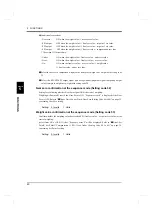
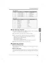
No. 15 “In operation (RUN)” is normally ON, and turns OFF in the following cases:
①
When an internal reset occurs due to overflow of the watchdog timer of the CPU.
②
When the exciter power supply voltage drops.
③
When a calibration error occurs.
④
When an input-over (plus/minus) error occurs.
⑤
When the digital zero adjustment value exceeds the DZ regulation value of code 45.
◆
The final error turns ON when the CPS set value > final set value.
■
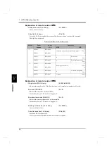
Input (Meanings of Signals)
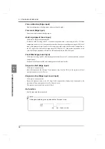
- Digital zero reset (Edge input)
Resets the zero point correction value by digital zero at the ON edge, and also cancels the zero
alarm if it has occurred.
- Digital zero (Edge input)
Zeros the gross weight at the edge input. However, the zeroing range is within the set digital zero
regulation value. If the value is outside this range, it is not zeroed but the weight error (zero alarm)
occurs.
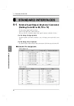
Pin No.
Port
Setting code
Initially-specified signal
10
External control input 0
70
0 (Digital zero reset)
11
External control input 1
71
1 (Digital zero)
12
External control input 2
72
2 (Tare subtraction)
13
External control input 3
73
3 (Tare reset)
14
External control input 4
74
4 (Hold or Judge)
Set value
Signal
Operation timing
0
Digital zero reset
ON edge
1
Digital zero
ON edge
2
Tare subtraction
ON edge
3
Tare reset
ON edge
4
Hold or Judge
Level
5
Feed/Discharge
Level
6
Sequence start
ON edge
7
Sequence stop
Level, ON edge
8
No function

