background image

2.CONNECTION

13

2-4. Connections to Terminal Block

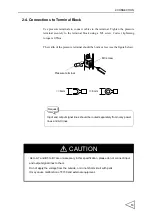
Use pressure terminals to connect cables to the terminal. Tighten the pressure
terminal securely to the terminal block using a M3 screw. Correct tightening
torque is 0.5Nm.

The width of the pressure terminal should be 6mm or less (see the figure below).

<= 6mm

<= 6mm

Pressure terminal

M3 screw

Input and output signal lines should be routed separately from noisy power

lines and AC lines.

Request

CAUTION

 A4 to A7 and B5 to B7 are unnecessary in this specification, please do not connect input

and output signal lines to them.

Do not apply the voltage from the outside, or do not short-circuit with parts.

It may cause malfunction of F159 and external equipment.

Summary of Contents for F159

Page 1: ...F159 07 Nov 2008 Rev 1 02 OPERATION MANUAL PLUG IN WEIGHT MODULE for the OMRON SYSMAC CJ1 SERIES PLC...

Page 2: ...resolution which increases the productivity of the weighing system The applications for the F159 weigh module includes Hopper scales Packing scales Bag filling systems Rotary filling systems and many...

Page 3: ...ollow divide into and and are indicated by the following documents Notes indicated here are the serious contents related to safety Please use F159 after understanding the contents well WARNING CAUTION...

Page 4: ...ing power Do not disassemble the main body for modifications or repair Be sure to ground the protective ground terminal When smoke a nasty smell or strange sound please shut off a power supply immedia...

Page 5: ...l output Take adequate shielding measures when using at the following locations Near a power line Where a strong electric field or magnetic field is formed Where static electricity relay noise or the...

Page 6: ...onnection 6 2 2 3 Connecting Load cells in Parallel 8 2 3 Output Connection 12 2 3 1 Equivalent Circuit 12 2 4 Connections to Terminal Block 13 3 DATA EXCHANGE WITH CPU 14 3 1 High Performance I O Uni...

Page 7: ...ibration 47 5 DISPLAY SETTINGS 50 5 1 Digital Filter 50 5 2 Analog Filter 50 5 3 Digital Filter 2 51 5 4 Motion Detection MD 52 5 5 Zero Tracking ZT 54 5 6 Digital Zero DZ 55 5 7 Digital Zero Clear 55...

Page 8: ...Under 78 6 5 Near Zero Upper Limit Lower Limit 79 6 6 U L Limit Comparison U L Limit Comparison Mode Near zero Comparison Over Under Comparison Over Under Comparison Mode 80 6 7 Complete Signal Outpu...

Page 9: ...ATION 108 12 1 Connection with CJ1 Unit 108 12 2 DIN Rail Installation 110 13 SPECIFICATIONS 112 13 1 Analog Section 112 13 2 Display 113 13 3 Setting 113 13 4 General Specifications 114 14 STATEMENT...

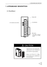
Page 10: ...minal block Unit number select switch DIP switch The switch is located beneath the terminal block CAUTION Terminal block can be detached by pulling down the lever Normally the lever should be in upper...

Page 11: ...n OFF Data exchange with CPU has been aborted ERC Red Error detected by the unit ON Error occurred in F159 OFF Normal operation ERH Red CPU error ON Error occurred during data exchange with CPU OFF No...

Page 12: ...l cause operation error Error Duplicate use of unit No Duplicate use of unit No in programming console disabling normal operation A40113 turns ON Switch No Unit No Channel number allocated to the I O...

Page 13: ...are set to ON position F159 can t operate normally Switch No State ON OFF 1 Calibration LOCK ON Calibration LOCK OFF 2 Default set ON Default set OFF 3 Undefined Undefined 4 Undefined Undefined NO 1 2...

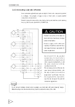
Page 14: ...59 terminal block EXC B1 S B2 EXC B3 S B4 RSV B5 RSV B6 RSV B7 OUT1 B8 OUT1 B9 A1 SHIELD A2 SIG A3 SIG A4 RSV A5 RSV A6 RSV A7 RSV A8 OUT2 A9 OUT2 Load cell signal F159 6 wire connection 4 wire connec...

Page 15: ...n F159 is also capable of 4 wire connection in which case additional jumper connections between B1 and B2 and B3 and B4 are required Although the system may function apparently correctly with B2 and B...

Page 16: ...abnormal heating and damage to the cell may result If you use F159 using 4 wire connection configuration never fail to connect between EXC and S and EXC and S Although the system may function apparen...

Page 17: ...l with a capacity multiplied by n and the same sensitivity with the constituent load cells The averaging resistor R takes the value between 300 and 500 with the same relative ratio and low temperature...

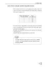
Page 18: ...r to drive the whole system including F159 and CJ series units CPU and I O units Select a power unit with ample capacity Depending on the specification of CJ series device used up to ten units can be...

Page 19: ...9 End cover F159 F159 Single load cell connection 0 58 A 0 08 A 0 10 A 0 30 A 0 30 A 0 30 A Power consumption Source capacity 5 V 2 8 A Unit type Unit name Qty Power consumption A CPU unit CJ1M CPU11...

Page 20: ...59 End cover F159 F159 Three load cells are connected in parallel 0 58 A 0 08 A 0 10 A 0 56 A 0 56 A 0 56 A Power consumption Source capacity 5 V 5 A Unit type Unit name Qty Power consumption A CPU un...

Page 21: ...120mA max User must provide an external power unit Vext 30 VDC to drive the output relay Do not short circuit the load such as a relay coil This may damage the output relay Use surge absorbing device...

Page 22: ...rminal should be 6mm or less see the figure below 6mm 6mm Pressure terminal M3 screw Input and output signal lines should be routed separately from noisy power lines and AC lines Request CAUTION A4 to...

Page 23: ...e high performance I O unit in the CPU unit based on the unit number The data is exchanged regularly every time I O refresh takes place Weighing setting data Settings for performing Weight measurement...

Page 24: ...9 High performance I O unit relay area 10CH Weighing Initial setting data D20000 n 100 D20000 n 100 99 Data memory DM area 100CH n unit number Weight value Weighing Initial setting data Weight data st...

Page 25: ...ON n 1 CH R W Request Span calibration Zero calibration 15 14 13 12 11 10 9 8 7 6 5 4 3 2 1 0 n 2 CH Gross weight 103 Gross weight 102 Gross weight 101 Gross weight 100 8 4 2 1 8 4 2 1 8 4 2 1 8 4 2...

Page 26: ...message will also be cleared HOLD While this bit is on 1 Weight value and Comparison Value remain unchanged hold HOLD bit 13th bit of n 5 CH remains high while HOLD is activated Digital tare subtract...

Page 27: ...rol sequence resulting in Sequence error 2 Error assistance code 3 Error code 2 While the system is in the state of sequence error Error assistance code 3 ON edge 0 1 in this signal resets the sequenc...

Page 28: ...ings m m 19 CH in DM area with CPU unit Direction of data transfer CPU F159 or F159 CPU is determined by R W bit R W The state of this line 1 0 at the time of REQUEST trigger 0 1 determines the direct...

Page 29: ...ng SP2 1 if Weight Final setting Set point 2 setting SP3 1 if Weight Final setting FF CPS setting Sequence mode Each bit is initialized to 1 when weighing sequence is started by SEQ Start s ON edge SP...

Page 30: ...ighing function 2 Complete signal output mode Time duration for which this signal is held 1 depends on the setting in complete signal output Over Under judgment disabled Criteria Judging times is set...

Page 31: ...gment is enabled Under 1 if Weight Final setting Under setting Over 1 if Weight Final setting Over setting Go 1 if Final setting Over setting Weight Final setting FF CPS setting Net weight 100 104 Ind...

Page 32: ...ero tracking is enabled For more information see Section 5 5 Zero Tracking ZT page54 HOLD in progress HOLD in Progress bit becomes 1 while Weight value is frozen Tare subtraction in progress This bit...

Page 33: ...1 while Zero calibration is in progress Span calibration in progress This bit becomes 1 while Span calibration is in progress NOV RAM This bit becomes 1 when NOV RAM is being accessed Do not remove p...

Page 34: ...ange OFL1 This bit is set 1 when Net weight Net Over setting OFL2 This bit is set 1 when Gross weight Capacity 9 scale intervals OFL3 This bit is set 1 when Gross weight Gross Over setting Zero error...

Page 35: ...plete normally TARE ON response Returns the state of TARE ON bit TARE OFF response Returns the state of TARE OFF bit DZ ON response Returns the state of DZ ON bit DZ OFF response Returns the state of...

Page 36: ...Q STOP response Returns the state of SEQ STOP bit Soft LOCK response Return the state of Soft LOCK bit Zero calibration response Returns the state of Zero Calibration bit Span calibration response Ret...

Page 37: ...00 Near zero 00000 99999 m 5 104 m 6 103 102 101 100 Set point 1 00000 99999 m 7 104 m 8 103 102 101 100 Set point 2 00000 99999 m 9 104 m 10 103 102 101 100 Free fall compensation 0000 9999 m 11 102...

Page 38: ...btraction m 32 100 100 100 100 Sequence mode m 33 100 10 1 101 100 Motion detection m 34 100 10 1 Zero tracking Period 0 0 9 9 m 35 103 102 101 100 Zero tracking Range 0000 9999 m 36 100 102 101 100 F...

Page 39: ...100 8 4 2 1 8 4 2 1 8 4 2 1 8 4 2 1 m 1 Undefined Undefined Undefined 104 8 4 2 1 m 0 1 1 1 0 1 0 1 0 0 0 0 0 0 0 0 m 1 0 0 0 0 0 0 0 0 0 0 0 0 0 0 0 0 CAUTION F159 and CPU unit exchange data in BCD f...

Page 40: ...value 3 ON when Gross weight Near zero set value 2 Comparison OFF 1 ON when Net weight Near zero set value 0 ON when Gross weight Near zero set value Upper Lower limit comparison 2 Compariosn OFF 1 N...

Page 41: ...emains on until Complete output time expires 1 After Compare time expires Complete signal turns on when reading becomes stable and remains on until Complete output time expires 0 Complete signal turns...

Page 42: ...selection 1 Digital tare subtraction ON 0 Digital tare subtraction OFF Avg count of free fall compensation Free fall compensation 2 Relay selection 1 Free fall compensation enabled 0 Free fall compen...

Page 43: ...selection Undefined Undefined 8 Near zero 7 Lower limit 6 Upper limit 5 Under 4 Go 3 Over 2 SP3 1 SP2 0 SP1 100 100 100 100 Undefined Digital tare subtraction expansion 1 inhibit 0 don t care Range o...

Page 44: ...onfirmation At start near zero confirmation 1 ON 0 OFF Auto jog 1 Enabled 0 Disabled Mode selection 1 Sequence control mode 0 Simple comparison mode 1 ON 0 OFF 100 10 1 101 100 Range 00 99 count Perio...

Page 45: ...ion selection 100 100 Motion detection mode Digital filter 2 1 Not used bypass 0 Use 128 samplings Undefined Undefined 1 Checker mode 0 Stable mode 100 100 1 4 scale division Decimal place 3 0 000 2 0...

Page 46: ...on the load cell That is F159 must be properly adjusted to indicate 100 kg when an actual load Weight of 100 kg is placed on the load cell sensing device This process is called an actual loading cali...

Page 47: ...0th bit of n 1 CH to 1 Register span value by loading the cell with actual span load and setting the Zero calibration bit 0th bit of n 1 CH to 1 Perform the Zero calibration procedure again if requir...

Page 48: ...is activated by setting a DIP switch The user must disable both of the LOCK features before trying to perform calibration procedures 1 Remove the terminal block F159 must be turned off before termina...

Page 49: ...and setting parameters The format can be selected from 0 0 0 0 00 0 000 Balance weight value Specify Weighteight value for Span calibration Input range 0 99999 Capacity Defines maximum allowable weig...

Page 50: ...umber 01 16 from the GA correction table for the region where actual load calibration will take place and then select a area number corresponding to the region where the system is installed Correct Gr...

Page 51: ...apetown 9 796m s2 Taichung 9 789m s2 Chicago 9 803m s2 Tainan 9 788m s2 Copenhagen 9 815m s2 Taipei 9 790m s2 Cyprus 9 797m s2 Tokyo 9 798m s2 Djakarta 9 781m s2 Vancouver BC 9 809m s2 Frankfurt 9 810...

Page 52: ...ading falls within the central two portions CZ bit 11th bit of n 5 CH will be set to 1 This function can be enabled disabled by the user 100 100 1 4 of scale division Decimal place Undefined Undefined...

Page 53: ...bration bit 0th bit of n 1 CH from 0 to 1 4 F159 starts Zero calibration procedures when it acknowledges an ON edge 0 1 of the Zero calibration bit 5 Zero calibration in progress bit 4th bit of n 6 CH...

Page 54: ...reading accuracy Use resistor with temperature coefficient better than 50ppm 5ppm class recommended Resistor Voltage shift equivalent strain Calculated Approximate value STRAIN mV V 875 K 866 K 200 0...

Page 55: ...e order If Calibration Error 3 persists while load direction and cable connections are correct Zero calibration must be performed again after inserting a resistor between EXC and SIG terminals of the...

Page 56: ...res must be performed while reading is stable 4 Toggle the Span calibration bit 1st bit of n 1 CH from 0 to 1 5 F159 starts Zero calibration procedures when it acknowledges an ON edge 0 1 of the Span...

Page 57: ...Span calibration is larger than Capacity setting Modify setting for Balance weight and or Span calibration and retry Span calibration Capacity and Balance weight value For accurate Span calibration B...

Page 58: ...e load cell are connected in reverse order Then perform Span calibration again Calibration Error 8 Load cell output is outside the F159 s allowable span adjustment range Check if the load cell is prop...

Page 59: ...t enhance response velocity Select optimal value according to the characteristics of each application 5 2 Analog Filter Analog low pass filter to remove undesirable noise components from the load cell...

Page 60: ...teria see Section 5 4 Motion Detection MD page52 100 100 Motion detection mode Digital filter 2 m 37 1 Not used bypass 0 Use 128 samplings Undefined Undefined Load cell Analog A D Digital Digital file...

Page 61: ...le bit 10th bit of n 5 CH to 1 Motion detection has two operation modes Stable mode and Checker mode Stable mode Each A D conversion data is compared with five previously acquired data D1 D5 see diagr...

Page 62: ...rence between current data and the data 0 09 second before The user can optionally insert digital filer when Stable bit becomes 1 to further reduce weight reading fluctuation See Section 5 3 Digital F...

Page 63: ...g clear Final to zero at every specified period if zero shift during that period remains within the specified range Allowed tracking period is from 0 0 to 9 9 seconds and Zero tracking range is from 0...

Page 64: ...is raised 13th bit of n 7 CH to clear digital zero and reset Zero Error bit 0 5 8 DZ Regulation Set value for DZ regulation specifies a range that allows Digital Zero and Zero tracking function to com...

Page 65: ...r Tare equalizing Net weight and Gross weight If Net weight and Gross weight are not equalized by resetting tare subtraction check the following Cause Suggested Action Gross weight is displayed Net we...

Page 66: ...fies condition for reading in tare value Always F159 can read in tare value anytime Stable F159 read in tare value only when stable bit 10th bit of n 5 CH is raised 1 Range of Tare Subtraction Specifi...

Page 67: ...material is drawn Discharge weighing Net weight will increase in negative direction Using this sign reversing function the user can obtain Net weight as a positive value To reverse the sign of Net we...

Page 68: ...ite an exact amount of material can be drawn from the source vessel by using a combination of such parameters and techniques including Final Set point 1 Set point 2 Free fall compensation Over Go Unde...

Page 69: ...om the raw material tank At first the feeding valves are to be fully opened to feed and closed in the order of large medium and medium small at the time of Final SP1 and Final SP2 respectively The fee...

Page 70: ...abled Travel of the raw material tank valve changes from medium to small 4 When the weight reaches Final FF CPS SP3 signal turns ON 11th bit of n 3 CH and the Compare time starts if enabled Feed valve...

Page 71: ...E SETTING AND OPERATION 62 0 Near zero Final SP1 Final SP2 Final FF CPS Final NET Over Under Time Tare subtraction SP1 output SP2 output SP3 output Comparison Compare time Near zero Judge inhibit time...

Page 72: ...raw materials are to be discharged from the metering tank to a container At first the Discharge valves of the weighing tank are to be fully opened to discharge raw materials and the Discharge valves...

Page 73: ...P2 signal turns ON 10th bit of n 3 CH and the Comparison inhibit time starts if enabled Travel of the raw material tank valve changes from medium to small 6 When the weight reaches Final FF CPS SP3 si...

Page 74: ...d weighing Tare subtraction SP1 SP2 SP3 Comparison Compare time Lower limit Judge inhibit time Go Over Under Gross weight is used for Upper Lower limit comparison Net weight is used for Final SP2 and...

Page 75: ...s Feed Discharge or Relay selection If you choose 2 Relay selection specify the type of Weighing mode by selecting Feed Discharge bit 6th bit of n CH 1 for Discharge control 0 for Feed control 100 100...

Page 76: ...lar interval The system outputs 1 when the preset condition is satisfied In this control method the next control operation is only enabled when measured weight falls below 75 of the previous Final val...

Page 77: ...H Conditional expressions Near zero outputs 1 when Weight value Near zero set value SP1 outputs 1 when Weight value Final SP1 SP2 outputs 1 when Weight value Final SP2 SP3 outputs 1 when Weight value...

Page 78: ...1 and one of these outputs subsequently changes to 0 depending on the result of control calculation Sequence control can be classified into following categories 1 Normal sequence control Control oper...

Page 79: ...ver Under comparison 0 Final SP1 Final SP2 Final FF CPS Final NET Over Under Time Tare subtraction Start Stop SP1 SP2 SP3 Complete Judge Over Go or Under Compare time ON ON OFF Complete t3 ON ON ON ON...

Page 80: ...arison inhibit time m 20CH t2 Compare time m 21CH t3 Complete output time m 22CH Conditional expressions Near zero outputs 1 when Weight value Near zero set value Start signal s ON edge 0 1 brings SP1...

Page 81: ...24CH is set to 00 Complete signal output is triggered by the transition of Final signal OFF edge 1 0 Note that the settings for complete signal output mode do not have effect here t1 Comparison inhibi...

Page 82: ...ettings for Over Under comparison mode Weighing function 2 parameters for m 28CH are ignored Upper Lower limit comparison is automatically performed at a regular interval ignoring settings for the Upp...

Page 83: ...e the stop signal is ON To recover the system from sequence error enter stop signal again 6 2 3 Mode Selection This parameter is used for defining simple comparison and sequence control mode operation...

Page 84: ...dd subtract the result of FF CPS value To minimize error user can set a regulation value to D Compensation can be performed automatically as long as the following relation holds Final regulation measu...

Page 85: ...030 Corrected value 5 20 020 0 020 1 0 530 6 20 000 0 000 2 0 530 7 20 010 0 010 3 0 530 8 20 110 0 110 3 0 530 9 20 010 0 010 4 0 0 530 0 040 4 0 010 0 010 2 4 0 005 Corrected value 10 19 880 0 120...

Page 86: ...9 104 m 25 m 26 100 100 100 100 Digital tare subtraction m 29 3 1 4 2 2 4 1 3 4 0 1 Avg count of free fall compensation Free fall compensation Free fall compensation coefficient Number of averaging 1...

Page 87: ...Near zero Final SP1 Final SP2 Final FF CPS Final Weight Over Under Time Near zero SP1 SP2 SP3 OFF ON ON ON ON OFF Over Go ON Under Parameter settings for Final discharge control Parameter Criteria equ...

Page 88: ...l equation Near zero 1 when Weight Near zero set value inpur range 0 99999 Upper limit 1 when Weight Upper Limt set value input range 0 99999 Lower limit 1 when Weight Lower limit set value input rang...

Page 89: ...d Over Under Options for each comparison function U L limit comparison Gross weight Net weight or Comparison OFF U L limit comparison mode Always or Judge input ON Near zero comparison Gross weight Ne...

Page 90: ...n Gross weight Near zero set value 2 Comparison OFF 1 ON when Net weight Near zero set value 0 ON when Gross weight Near zero set value 100 100 100 100 Sign convention for discharge control m 28 3 Com...

Page 91: ...ratio for a specific period of time Complete Signal Output Mode and Complete output time These two parameters define the output timing of Complete signal and its duration Complete signal outpu mode Co...

Page 92: ...ime expires or It turns on when reading becomes stable and remains on until Complete output time expires 1 After Compare time expires Complete signal turns on when reading becomes stable and remains o...

Page 93: ...FF CPS Judging times 2 times Average count of FF CPS 2 times FF CPS reads in and stores samples for compensation synchronized with Over Under comparison signal Selecting 00 for Judging times inhibits...

Page 94: ...t Lower Limit page79 At start WV confirmation You can enable disable the F159 to check if the weight is equal or larger than SP1 point Final SP1 set value Sequence Error 5 is generated if the initial...

Page 95: ...allowed only in the Sequence mode If Over Under check decides that the weight is stll short of the desired value Under SP3 will turns ON again until Auto jog timer expires 101 100 101 100 Judging time...

Page 96: ...nput and output range are as follows Net weight Over input range 0 99999 Gross weight Over input range 0 99999 Conditional equation Output Net weight Over Net weight Net weight Over set value 10th bit...

Page 97: ...021 0 D20001 Upper limit MOV 021 0 D20002 Lower limit MOV 021 0 D20003 Lower limit MOV 021 0 D20004 Near zero MOV 021 0 D20005 Near zero MOV 021 0 D20006 Set point 1 MOV 021 0 D20007 Set point 1 MOV...

Page 98: ...ut time MOV 021 0100 D20023 Auto jog timer MOV 021 0101 D20024 AZ times Judging times MOV 021 9800 D20025 FF CPS regulation MOV 021 0000 D20026 FF CPS regulation MOV 021 0000 D20027 Weighing function...

Page 99: ...0021 D20038 Function selection MOV 021 0000 D20039 Balance weight MOV 021 0001 D20040 Balance weight MOV 021 0000 D20041 Capacity MOV 021 0001 D20042 Capacity MOV 021 0001 D20043 Minimum scale divisi...

Page 100: ...data R W RSET Q2001 12 Request RSET 100 00 Final write start SET 100 01 Final data set 100 01 000003 Final data set 000057 Request RSET 100 01 Final data set SET 100 02 Wait for write I 2009 12 Reque...

Page 101: ...Wait for a read I 2009 12 Request SET Q2001 12 MOV 021 50 D301 Wait for completion 100 05 000007 Wait for a read 000081 Wait for a read complete SET 100 06 Read complete D301 Wait for a read 300 0 D30...

Page 102: ...uses decrement counters step 000004 and 000007 for counting Write complete and Read complete To trigger FINS command for exchanging data with CPU unit F159 sends Request bit to CPU This is required b...

Page 103: ...Read complete 100 07 BOOL Start comparison 100 08 BOOL Comparison complete 200 13 BOOL Final setting error For read write error detection 2001 12 BOOL Request F159 relay area 2001 14 BOOL R W 2009 12...

Page 104: ...Refer to m m 1 Upper limit 00000 P 79 m 2 m 3 Lower limit 00000 P 79 m 4 m 5 Near zero 00000 P 79 m 6 m 7 Set point 1 00000 P 78 m 8 m 9 Set point 2 00000 P 78 m 10 Free fall compensation 0000 P 78 m...

Page 105: ...on 12 P 34 m 31 Restriction on the tare subtraction function 0000 P 34 m 32 Sequence mode 0000 P 35 m 33 Motion detection 1505 P 52 m 34 Zero tracking Period 00 P 54 m 35 Zero tracking Range 0000 P 54...

Page 106: ...lue exceeds the F159 s zero adjustable range 2 Calibration Error 3 Initial Tare value is in negative territory 3 Calibration Error 4 Balance weight is larger than Capacity 4 Calibration Error 5 Balanc...

Page 107: ...calibration Correctly performed Zero calibration will clear the error message Name Description Error Code Sequence Error 1 Stop signal had been raised when the system tried to start weighing sequence...

Page 108: ...reading accuracy Use resistor with temperature coefficient better than 50ppm 5ppm class recommended Resistor Voltage shift equivalent strain Calculated Approximate value STRAIN mV V 875 K 866 K 200 0...

Page 109: ...he load cell for shifting zero point See the table in the previous section Calibration Error 2 for determining the resistor to be inserted Calibration Error 4 Value set for Balance weight and or Span...

Page 110: ...erform Span calibration again Calibration Error 7 Load cell output varies in negative range Check if the cell is loaded in opposite direction or SIG and SIG of the load cell are connected in reverse o...

Page 111: ...ow Check all the cables for proper connection between F159 and the load cell and if any of the cables are overloaded Span adjustable range for F159 is from 0 3 to 3 2 mV V within which the Span value...

Page 112: ...restore normal weight display reduce the signal from the load cell until OFL1 bit 10th bit of n 7 CH turns off or modify the set value for Net over OFL2 Gross weight Capacity 9 scale division Gross we...

Page 113: ...uto zero in using sequence control To clear ZALM remove the cause of zero shift adherence of foreign object etc and reset Digital Zero Change stop signal from OFF to ON to remove the sequence error Se...

Page 114: ...between the set values for SP1 and Final and then check the following Sequence started prematurely while material still remains in the metering tank Start turned ON prematurely Material can not be dis...

Page 115: ...ting FRAME F G EXC S S EXC SIG SIG Internal Control Zero Gain Filter CPU 16bit NOV RAM 4096bit External Status CJ1 bus control LED Electrically DC DC DC5V IN 8V 8V Electric isolation by photo couplers...

Page 116: ...11 DIMENSIONS 107 11 DIMENSIONS Unit mm...

Page 117: ...J series do not require base unit Each unit can be connected to each other using the integrated side mount connector PA205R POWER INPUT AC100 240V L2 N L1 DC24V AC240V OUTPUT RUN PERIPHERAL ERR ALM RU...

Page 118: ...1G CPU44 SYSMAC PROGRAMMABLE PORT OPEN BUSY MCPWR Slide the slider towards the back Locked Released Slider of the unit until it clicks CAUTION Lock the unit securely by moving the slider to its full s...

Page 119: ...unted to DIN type rail It can no be installed using screws 1 Set the DIN rail pins on the rear of the unit to Released position 2 Hook the CJ unit s upper protrusions on the DIN rail and engage the en...

Page 120: ...of endplates from both sides Fook lower notch of the end plate to the lower plate of the rail and then engage the upper notch then pull the end plate to lower direction Tighten the screw to fix them...

Page 121: ...ion Span adjustment 0 3 3 2 mV V Coarse Digital control using the coarse adjustment circuit Fine Automatic adjustment using digital calculation Max sensitivity 0 3 V count Auuracy Linearity error 0 01...

Page 122: ...mance I O unit 0 95 DIP switch Lock function Set value Inported from CJ1 Set value storage Initial values NOV RAM non volatile RAM Set value protection Modificatio of set values can be inhibited to pr...

Page 123: ...tion At start weight value confirmation Motion detection period range Zero tracking period Zero tracking range Filter Analog filter Digital filter Stable mode Digital filter 2 Motion detection mode Fu...

Page 124: ...t the devices and machines into which F159 is built can more easily conform to EMC standards The actual F159 has been checked for conformity to EMC standards Whether these standards are satisfied for...

Page 125: ...14 STATEMENT OF CONFORMATION TO EC DIRECTIVES 116 M E M O...

Page 126: ...Unipulse Corporation 9 11 Nihonbashi Hisamatsucho Chuo ku Tokyo 103 0005 Tel 81 3 3639 6120 Fax 81 3 3639 6130...

Reviews: