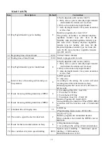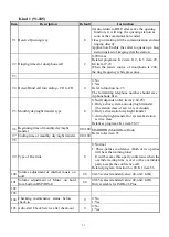
16
1.10 Connecting Instruction of Interface Card
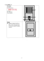
1.10.1 F9910 Doorphone Card (DHVR)
Description
:
P1, P2: Connect to JP3 & JP4 of CPU card
or JP2 & JP4 of last expanding
card by Ribbon cable
P3: Electronic door lock and doorphone
U3
P1
P2
U1
P3
1
23
4
5
67
8
RY1
U2
F9910
Doorphone
Card
Installation of Electronic door lock(P3):
Pin1: Door lock connector (EL); EL controls
the DC electronic lock directly. The
power is supplied by system.
Pin2, P3: Connect to A
Pin4: Checking Switch (PT) of door status
(Open/close status)
Door Phone
EL
A
PT
P3
D
O
O
R
PH
O
N
E
Ele
ctr
on
ic L
O
C
K
1
2
3
4
5
6
7
8
Electric Door lock
Uniphone
Installation of Doorphone(P3):
Pin5,6: connect to P1(1,2), Please switch
the wire as (2,1) if LED of the
doorphone not light-on (polarity
opposite).
Pin7,8: number key 2-3 of door phone.
Ringing group S2-S3 (for 3
buttons doorphone only).


