20
1.11 Connecting Instruction of Accessories
1.11.1 STA-SLT Converter Unit (SLT-2DA)
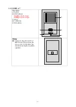
CHANNEL SELECT
L0 L1 (L0&L1)
DIGITAL LINE
INPUT
OUTPUT
SLT
(L1)
SLT
(L2)
(-)
(+)
Description:
INPUT: Connected with the digital station port (2 wires)
OUTPUT: Connect with the single line phone (normal phone)
CHANNEL SELECT: L1- for L1 SLT; L2 – for L2 SLT; L0&L1: for 2 SLT
Notice:
The max. distance from KSU to converter is 10m. The max. distance between
single line telephone and single line port is 200m.
1.11.2 ISDK2-DISA
RUN REC PLY
1
PLY
2
LED Indicator:
RUN
Flashing: in work
OFF: Faulty
PLY1
ON: In playing
OFF: Idle
REC
ON: In recording
OFF: Idle
PLY2
ON: In playing
OFF: Idle
EXT
DC
BATT
OUT
- + - +
SW
RST
L0 L1 (L0&L1)
TO
NEXT
TEL
LINE
Description
:
Line
: Connected with the digital station port.
TEL
: Connect with normal phone to program/record directly.
TO NEXT
: Connect with next DISA
SW
: Three selections: L0: only connect with L0 loop; L1: only connect with L1 loop;
L0&L1: connect with L0 and L1 loops.
RST
: Reset
EXT DC
: Connect with backup battery while used as 1
st
DISA.
DC OUT
: Please connect "DC_OUT" of 1
st
DISA with "EXT_BATT" of 2
nd
DISA when
there’re 2 DISA connection.
Notice
:
1. The max. distance from KSU is 10m.
2. L0 and L1 should be the same station loop
.


