background image

Chapter 

3

  LED  Display  Control  Setting 

43 


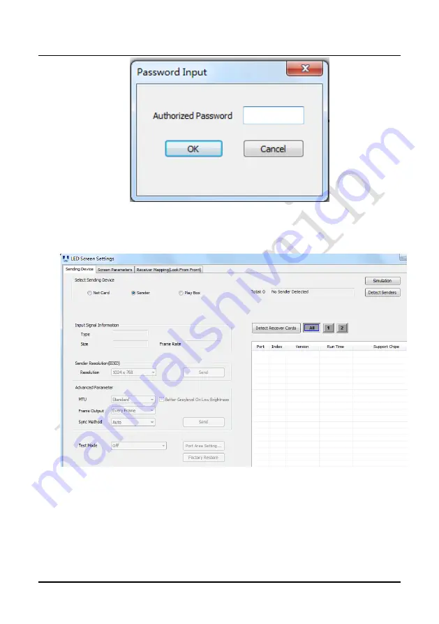
Fig 3-28 Enter the Password 


Fig 3-29 LED Screen Settings 

3.4.2.2 Set the Sending Card 

1) Detect Senders 

Enter the LED Screen Settings interface, select the “Sending Device” page, and 

then click “Sender” → “Detect senders”. If the sending card is detected, the “Sending 

Summary of Contents for UHWII Series

Page 1: ...UHWII Product Manual I...

Page 2: ......

Page 3: ...ate 01 Initial release July 25 2019 02 Optimized installation September 24 2019 03 Add After Sales and Warranty Modify the control system part Add module flatness adjustment Add Concave Installation M...

Page 4: ...our best to help you resolve the problems in time and highly appreciate your suggestions Copyright The manual is the property of Unilumin Group Co Ltd The Unilumin LED s operating software is develop...

Page 5: ...o the LED display 5 Do not place or use the LED display in an environment with volatile corrosive or flammable chemical products 6 Do not use the LED display outdoors in rainy days or when the humidit...

Page 6: ...total power consumption not exceeding 3 kW and three phase power supply for an LED display with the total power consumption exceeding 3 kW 5 Ensure that the LED display is powered on at least twice pe...

Page 7: ...Module Flatness Adjustment 16 2 4 Wiring for LED Display 17 2 4 1 Common Cables 17 2 4 2 Signal Cable Connection 18 2 4 3 Power Cable Connection 20 2 4 4 Smart Control Distribution Box 22 Chapter 3 L...

Page 8: ...a Playing Solution 54 4 1 2 Playing Setting 55 4 1 2 1 Display Window Setting 55 4 1 2 2 Startup Setting 56 4 1 3 Editing Professional Playing Solution 57 4 1 3 1 Editing the Time Segment 57 4 1 3 2 E...

Page 9: ...ing of a Cabinet in the Display 89 6 1 5 Failure in Lighting up of a Cabinet in the Display 89 6 1 6 Failure in Lighting up Part of the Modules in the Cabinet 90 6 2 Replacement of Main Components 90...

Page 10: ...UHWII Product Manual VIII Contact Information...

Page 11: ...ixel calibration technology can greatly improve experience of using the UHWII series product in projects Outstanding safety design of the UHWII series delivers prominent safety performance high protec...

Page 12: ...ft right shoulder screw hole rear maintenance 3 Left right shoulder screw hole front maintenance 4 Cabinet mounting hole 5 Module 6 Upper lower shoulder screw hole rear maintenance 7 Upper lower shoul...

Page 13: ...frequency Hz 50 60 Data interconnection Signal cable 100m Multi mode fiber 300m Single mode fiber 10km Optical parameter Brightness nits 600 800 Color temperature K 2 000 9 500 adjustable Viewing angl...

Page 14: ...ion The display system consists of the LED display sending box control PC matrix splicing controller and power distribution box refer to the shipping list for details The following shows a topology of...

Page 15: ...sembled seamlessly into a screen of any size and are extensively used as fixed LED displays for advertisements in public places such as retail brand stores shopping malls hotels banks churches airport...

Page 16: ...ency is found contact us in time The main components include cabinets signal cable power cable USB cable DVI cable and sending box For details about the components refer to the shipping list 2 2 Gener...

Page 17: ...cabinets with socket head cap screws 3 Keep flatness between the cabinets during cabinet installation 4 After the installation of the cabinet is completed Connect the power cable and the signal cable...

Page 18: ...Chapter 2 Installation and Wiring 8 Fig 2 4 Front View of Cabinet Installation Fig 2 5 Front View of Single Cabinet Module Number Fig 2 6 Front View of the Display...

Page 19: ...whether the bottom beam is level Make sure that its levelness is within 1mm 2 Install the cabinets sequentially from bottom to top and from middle to both sides Fasten the adjacent cabinets with scre...

Page 20: ...2 Installation and Wiring 10 Fig 2 11 Cabinet Fastening Fig 2 12 Rear View of the Display Fig 2 13 Rear Connecting Plate front Fig 2 14 M10 x 60 socket head cap screws rear Square Tube Connecting Pla...

Page 21: ...bolts 4 After the first line of cabinet is installed the second line of cabinet is installed and the upper and lower cabinets are fixed with upper and lower shoulder screw 5 In the process of cabinet...

Page 22: ...Chapter 2 Installation and Wiring 12 Fig 2 16 Upper and lower cabinet locked Fig 2 17 Rear Connecting Plate front Mounting plate and socket head screws...

Page 23: ...re fixed with M6 plug bolts as shown in Fig 2 23 the mounting plate and cabinet are fixed on the square pipe with hexagon socket bolts 4 After the first line of cabinet is installed install the second...

Page 24: ...Chapter 2 Installation and Wiring 14 Fig 2 20 Splicing of left and right cabinet s Fig 2 21 Internal drawing of left and right cabinet splicing Angle block M6 plug bolts...

Page 25: ...Chapter 2 Installation and Wiring 15 Fig 2 22 Splicing of left and right cabinets completed Fig 2 23 Rear Connecting Plate front...

Page 26: ...djustment tool to adjust the magnet on the box At the low end the module regulates the adjustable magnets until the module is flush with the adjacent modules one module has 9 adjustable magnets Specif...

Page 27: ...Fig 2 27 Schematic diagram of module flatness adjustment 2 4 Wiring for LED Display 2 4 1 Common Cables Incoming Power Cables Power Cable Passing Through Cabinet DVI Cable Incoming Signal Cable USB Ca...

Page 28: ...shows the signal cable connection for display with a resolution of 1920 x 1090 Signal cables shall be connected based on the wiring diagram of the delivered products for the project Fig 2 28 Signal C...

Page 29: ...Chapter 2 Installation and Wiring 19 Fig 2 30 Signal Cable Connection Diagram of UHWII 1 9 Fig 2 31 Signal Cable Connection Diagram of UHWII 2 5...

Page 30: ...7 shows the power cable connection for display with a resolution of 1920 x 1090 Power cables shall be connected based on the wiring diagram of the delivered products for the project Fig 2 32 Power Cab...

Page 31: ...Chapter 2 Installation and Wiring 21 Fig 2 34 Power Cable Connection Diagram of UHWII 1 9 Fig 2 35 Power Cable Connection Diagram of UHWII 2 5...

Page 32: ...ed start stop function allowing you to set any time for the LED display to be remotely started or stopped Fig 2 36 Internal Structure of Distribution Box SN Component Remark s 1 Main switch MCCB 2 Tem...

Page 33: ...trol distribution box The PLC communication system is RS485 It uses converter from control computer RS232 to RS485 For more detail information please refer to our Intelligent Power Distribution Manage...

Page 34: ...reliable contact with the ground and kept away properly from the live wire The connected power supply shall be distant from high power equipment 3 When the 3 phase and 5 wire system is adopted the loa...

Page 35: ...the sending box is blinking normally blinking once per second Fig 3 1 Replication Mode 3 3 Unilumin N series Software Control Setting 3 3 1 Installing the Software 7 Open the optical disk provided for...

Page 36: ...is 1 Click the User option and select Advanced Login as shown in Figure 3 3 Fig 3 3 Main Window of UniLCT Mars Enter the initial password admin as shown in Figure 3 4 to go to the advanced user windo...

Page 37: ...e 3 6 Fig 3 6 Screen Configuration The following window is displayed Set Sending Board Resolution 1920 1080 recommended Set Graphics Output Resolution to the same value as Sending Board Resolution The...

Page 38: ...rd page click Scan Board to display the following window Fig 3 8 Scan Board Configuration 1 Click Load File to load the file xxxx rcfg stored in the optical disk 2 Click Send to HW 3 After sending con...

Page 39: ...configuring the parameters on the Scan Board page click Screen Connection to display the following window 1 Click Read File to load the file xxxx scr stored in the optical disk as shown in Figure 3 9...

Page 40: ...m that the screen is complete Then click Save Fig 3 10 Screen Connection with Loaded File 3 3 3 Brightness Adjustment On the main window click Brightness as shown in Figure 3 11 to display the brightn...

Page 41: ...e brightness value the maximum value is 255 next to the scroll bar Fig 3 12 Manual Adjustment Display Quality Includes Soft mode and Enhanced mode The Soft mode is generally used for indoor LED displa...

Page 42: ...izard 3 3 4 Correction Coefficient Management The UTWII series products have been subject to correction before shipment To ensure the optimum displaying effect of the screen you need to activate the c...

Page 43: ...nt database Set coefficients for a new scan board After replacing the scan board receiving card set the correction coefficients for the new receiving card Set coefficients for a new module After repla...

Page 44: ...Card 1 As shown in Figure 3 15 select Topology or List Select the position of the replaced receiving card Click Next Fig 3 15 Selecting Area for New Receiving Card 2 Select the coefficient source Clic...

Page 45: ...play Control Setting 35 3 Select the corresponding correction coefficients Fig 3 17 Selecting Correction Coefficients for Receiving Card 4 Select Stable Upload and click Next Fig 3 18 Uploading Correc...

Page 46: ...ent Red Adjust the red brightness value of calibration coefficients Green Adjust the green brightness value of calibration coefficients Blue Adjust the blue brightness value of calibration coefficient...

Page 47: ...odule Select Topology or List Then select the position of the receiving card where the new module is located Double click the selected position Fig 3 21 Selecting Cabinet for the New Module 2 Choose D...

Page 48: ...teps of coefficient adjustment in setting coefficients for a new scan board For details refer to Step 2 and Step 3 in Section 3 5 1 4 Save the correction coefficients to the hardware Use similar steps...

Page 49: ...e make sure that the receiving have read coefficient from the Flash and save Click Setting on the main window and select Module Flash as shown in following fig Main Window Click Check Coefficient in M...

Page 50: ...save a picture as the prestored picture for the screen This prestored picture can be set as a screen displayed upon booting signal cable disconnection or DVI signal absence On the main window click T...

Page 51: ...ave to Hardware to save the picture as a prestored picture to the hardware Click Check Store Picture to display the stored picture on the screen so as to check its effect 2 Function Settings Boot Scre...

Page 52: ...in the optical disk to the control PC Fig 3 26 Software Installation NOTE You can follow the software installation wizard to install the software 3 4 2 Display Configuration 3 4 2 1 Login to the Displ...

Page 53: ...8 Enter the Password Fig 3 29 LED Screen Settings 3 4 2 2 Set the Sending Card 1 Detect Senders Enter the LED Screen Settings interface select the Sending Device page and then click Sender Detect send...

Page 54: ...ty the input signal information of the sending card etc as shown below Fig 3 30 Detect Senders Fig 3 31 Sending Card Information 2 Input Signal View After detecting the sending card if the video signa...

Page 55: ...45 Fig 3 32 Input Signal Information 3 Settings the Sending Card Parameters After detecting the sending card can make some settings on the sending card parameters on the Sending Device page Fig 3 33...

Page 56: ...d card interface click Screen Parameters to set the screen parameters 1 Click Load to load the xxxx rcvbp file on the CD 2 Click Send 3 After sending is complete confirm that the display screen menu o...

Page 57: ...connect the display 1 Click Load load the xxxx mapping files on the disc 2 Click Send 3 After sending is complete confirming that the display screen menu is normal click Save to Devices to save Fig 3...

Page 58: ...adjust the brightness automatic adjustment of multi function card timing brightness adjustment manual adjustment white balance adjustment brightness correction adjustment etc 1 Manual adjustment In th...

Page 59: ...htness Adjustment 2 Automatic brightness adjustment In the brightness adjustment interface check Enable auto adjust and click Save to Multi function Card The brightness is the current brightness perce...

Page 60: ...oefficients for a New Module 1 First set the window to be greater than or equal to the actual screen pixel size Fig 3 40 Screen Size and Count 2 In the main window click Control By Point Calibration B...

Page 61: ...reen Information Read get screen information and read back the screen correction coefficient Fig 3 42 Brightness Calibration 4 Click Import By Region Normal to import the correction coefficient of the...

Page 62: ...52 5 Enter the location of the module that needs to resend the correction coefficient Fig 3 44 Starting Point Setting 6 Selecting a correction coefficient file for the module of the corresponding are...

Page 63: ...k Send to enable brightness correction Fig 3 46 Brightness Calibration 8 Open the LED screen setting window on the screen parameter page select Brightness in the Calibration Mode select From Receiver...

Page 64: ...ng program Professional playing program and Priority programs of the page Professional playing program is used most commonly This Section introduces the Professional playing program only Run the softw...

Page 65: ...ows To increase or decrease the number of display windows re enter the number of display windows in the box next to Number of Display Windows and then click Update Start X Indicates the horizontal sta...

Page 66: ...xt time when the PC is started Restart Software on Time If you enable this function set the restart interval and time and click OK UniStudio will be automatically restarted after the PC time reaches t...

Page 67: ...is function the PC will automatically read and activate the playing solution once the USB flash drive is inserted to the PC If you do disable this function the PC cannot implement the plug and play fu...

Page 68: ...perties of the playing solution After adding a general time segment or interstitial segment click General Segment 1 to edit the properties displayed in the segment editing area on the right side as sh...

Page 69: ...click General Segment or click the Add Global Program Page in the toolbar to create a program page Fig 4 7 Creating a Program Page 2 Setting the properties After creating the program page click Progr...

Page 70: ...after the preset Times to Play for the display window with the longest playing time on the current program page has been reached If you select Specify Duration the next program page is played after t...

Page 71: ...displayed in the area not covered by the display window as shown in Figure 4 9 Fig 4 9 Background of Program Page After adding the program page you can move copy paste or delete the program page by us...

Page 72: ...you need to add a display window to this program page Click Add Window on the toolbar of the program page to add a window to the current program page See Fig 4 11 Fig 4 11 Adding a Window to Program P...

Page 73: ...can be adjusted based on actual conditions by using either of the following two methods a Directly specify the new location and size in the setting pane as shown in Fig 4 13 Fig 4 13 Setting the Wind...

Page 74: ...ndow to be deleted Click the delete key to delete the window as shown in Fig 4 15 Fig 4 15 Deleting the Display Window 4 Moving a display window Select the program or window Click the direction key to...

Page 75: ...r adding the media is Common Window Click the Add Media button of a common window to select media of different types to be added into the media list See Fig 4 17 Fig 4 17 Adding the Media After adding...

Page 76: ...s property page you can change the properties of the medium See Fig 4 19 Fig 4 19 Properties of Medium 3 Editing the media in the common window In an actual application if different playing times are...

Page 77: ...pter 4 LED Display Playing Setting 67 Modify Fig 4 20 Changing the Media Playing Times Right click the media to perform operations on the selected media as shown in Fig 4 21 Fig 4 21 Media Operation M...

Page 78: ...in Fig 4 22 Fig 4 22 Media Playing Menu 4 1 3 5 Playing the Media After the playing mode is edited or loaded click the play key on the main toolbar to start the current playing mode as shown in Fig 4...

Page 79: ...Information Page Clicking Pause or Stop on the toolbar can pause or stop the currently played program You can also perform this operation by using the operation menu that appears when you right click...

Page 80: ...ock window you need to click Pause perform the Move Up operation to move the clock window to the front side of the common window and then click Play If the clock is displayed transparently the clock w...

Page 81: ...ting 71 Fig 4 27 Saving a Playing Solution File Open After a playing solution is saved you can directly click Schedule in the toolbar and select Open to open the playing solution See Fig 4 28 Fig 4 28...

Page 82: ...e Count and Size of the Screen Open the software click Control Screen Size and Count Settings in the main window as shown below Fig 4 29 Main Window Set the count of LED screens and the starting posit...

Page 83: ...t is played continuously during playback can contain multiple windows Only one global page can be set per screen Normal Page The normal page can contain multiple windows and each normal page can have...

Page 84: ...ter 4 LED Display Playing Setting 74 2 After creating the program page click the Add button or right click on the program page node to bring up the add program window menu Fig 4 33 Add Program Window...

Page 85: ...ing the file window select the file window and click the Add button to select the desired material Fig 4 34 Material Menu 4 After adding the material can set the material properties in the property bo...

Page 86: ...width of the window in pixels Height The height of the window in pixels Window operation icon For window shortcuts there are left right top bottom and maximize Border To set the width of the window b...

Page 87: ...ying Setting 77 4 2 4 Playing the Program 1 Play the current program file click the play button or click the main window Play Play to start playing Fig 4 37 Play the Current Program File Fig 4 38 Play...

Page 88: ...same time Set the playback content click the program page that want to play or click the File Open button to open the file that want to play then click Play Play to play multiple programs The program...

Page 89: ...click the delete button to delete the material window or right click on the material window to be deleted and in the pop up options click Delete as shown below Fig 4 41 Delete 2 Copy Select the windo...

Page 90: ...st window 2 Click Add to add an instruction In the Timing Command List window set the execution content and time of the instruction If there are multiple instructions repeat the operation 3 The detail...

Page 91: ...Chapter 4 LED Display Playing Setting 81 Fig 4 44 Timing Command List Fig 4 45 Action Table...

Page 92: ...Chapter 4 LED Display Playing Setting 82 Fig 4 46 Timing Command List Fig 4 47 Setting Timing Command List...

Page 93: ...ions for the LED display on a daily basis 2 Use the LED display and its auxiliary devices at least twice a week and two hours each time Before using the LED display perform warm up operations if it ha...

Page 94: ...This setting is for warm up operation only You do not need to set the prestored picture if the LED display is used frequently 5 4 1 Unilumin N series Setting the Prestored Picture For details about h...

Page 95: ...ghtness adjustment interface as shown in Fig 5 2 Figure 5 2 Main Window for Advanced User Select Manual and set the brightness to 26 the brightness is about 10 by dragging the scroll bar below Brightn...

Page 96: ...l interface Set Self Test to White Click Send to finish the operation As showed in Fig 5 4 and Fig 5 5 Fig 5 4 Display Control Fig 5 5 Display Control Adjust the screen brightness and perform ageing b...

Page 97: ...splay is not used for 14 consecutive days please follow the instructions below for aging before using it again In the main window click Test Aging Test to enter the aging interface Drag the playback w...

Page 98: ...reliably 3 Check whether the control PC is in sleep mode or monitor protection mode If the control PC is not in sleep mode check whether the graphics card is configured properly on the software 6 1 2...

Page 99: ...the resolution of the screen 6 1 4 Blinking of a Cabinet in the Display Causes 1 The output of receiving card or hub card is faulty 2 The receiving card program is incorrect Troubleshooting method 1...

Page 100: ...the hub card ports or flat cables that control the modules 6 2 Replacement of Main Components Before performing maintenance on the LED display cut off the power supply to ensure your personal safety...

Page 101: ...ling Replace a module of the LED display based on the following steps Step Picture Description 1 Locate the faulty cabinet Disconnect the power cable and signal cable 2 Use a tool to suck out the faul...

Page 102: ...y replace a power supply of the LED display based on the following steps Step Picture Instruction Operation 1 Locate the faulty cabinet remove the faulty module 2 Locate the faulty power supply remove...

Page 103: ...teps Step Picture Instruction Operation 1 Locate the faulty cabinet Disconnect the power cable and signal cable 2 Use a tool to suck out the faulty module 3 Locate the faulty power supply remove the f...

Page 104: ...supply of the display replace receiving card of the LED display based on the following steps Step Picture Instruction Operation 1 Locate the faulty cabinet remove the faulty module 2 Disconnect the wi...

Page 105: ...on the following steps Step Picture Instruction Operation 1 Locate the faulty cabinet Disconnect the power cable and signal cable 2 Use a tool to suck out the faulty module 3 Disconnect the wire conne...

Page 106: ...The cabinets must be packaged before transportation The product shall not be placed upside down or horizontally and must be protected against the wind rain direct sunlight and corrosive liquid during...

Page 107: ...s and manufacturing during normal use Unilumin provides warranty service for Products under this Warranty Policy 8 3 1 Warranty Service Types 1 Online Remote Free Technical Service The remote technica...

Page 108: ...quality problems is not covered by this Warranty Policy after the on site investigation of Unilumin s engineer customer shall pay travel expenses and technical service fees as per Article 7 4 Defectiv...

Page 109: ...ss and color under normal conditions Normal degradation in the performance of the Product normal wear and tear 11 Lack of necessary maintenance 12 Other repairs not caused by product quality design an...

Page 110: ...se be cautious about the package and protection of the products Unilumin is not responsible for any damages to the returned products or parts during delivery 3 On site Engineer Service Process Submit...

Page 111: ...anty Card Product Warranty Card Order No Shipment Date Warranty Period Product Model Product Quantity Customer Name Contact Information Customer Address Remark s Warranty Record Warranty Date Fault an...

Page 112: ...Attachment 2 Path of Signal Cable inside the Cabinet 102 Attachment 1 Path of Signal Cable inside the Cabinet Cabinet Cable Connection Diagram of UHWII Front View...

Page 113: ...sheng Fifth Road western Daya Bay Huiyang District Huizhou Telephone switchboard 86 0 755 29918999 Fax 86 0 755 29912092 Website www unilumin com Service Department Tel 86 0 755 29592226 direct line 2...

Page 114: ...West 950 Great West Road Brentford Middlesex TW8 9ES E mail sales unilumin com Tel 44 0 208 568 6333 RUSSIA POST SALE SERVICE CENTER Address Russia 111250 Moscow Zavoda Serp I Molot Drive D 10 Tel 86...

Page 115: ...29918999 61 3 9827 8374 E mail amer support unilumin com sales_au unilumin com MIDDLE EAST SUBSIDIARY Address Suite 1702 Reef Tower cluster O Jumeriah Lake Towers Dubai UAE Tel 00971 4 4270171 E mail...

Page 116: ......

Page 117: ......

Page 118: ......

Reviews: