background image

MSR110D Programmer’s Manual                                                            UDN PM008 Rev. D 
Section 4 – Commands and Responses                                                                                                                                2002/3/19


Page 

12


Uniform Industrial Corp.

  Proprietary and Confidential

                                                                                              Total 44 pages


Section 4    COMMANDS and RESPONSES


This section describes the commands and responses available for the MSR110 series. Each item includes the ASCII, 

hexadecimal codes and comments paragraph. The comments paragraph provides an explanation of the command. The 

letter ‘x’ indicates a variable and the letter 'h' is an abbreviation of 'hexadecimal'.   

All readers are capable of communicating in 3 protocols: 0, 1 and 2. If protocol 0 is selected, all commands and 

responses are as listed in this section. If protocol 1 is selected, the characters STX, ETX and BCC must be added to all 

transmissions. If protocol 2 is selected, the characters SOH, ADDRESS, COUNT and BCC must be added to all 

transmissions. 


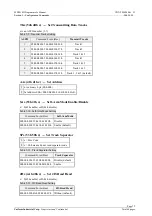
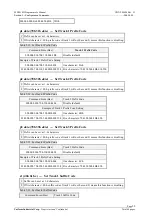
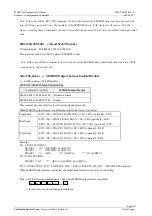
Command 

 Host to Reader 


P (50h) 

  Ready to Read 

Comments


1  Clear buffers 

2  Transmit "ACK" 

3  Expect for card swipe 

4  Transmit "ACK" after card swipe 

After an "Ready to Read" command is received and acknowledged, the only valid commands that will be accepted 

for execution are: "Abort" <ESC>, "Status" <$> and LED control commands. When the reader is ready for "Read 

on Insert", the "ACK" after card swipe will be transmitted after the rear sensor is activated. For read on reverse 

swipe, the "ACK" after card swipe will be transmitted after the front sensor is de-activated. 


p (70h) 

  Ready to Read 

Comments 

Same as 'P' command, except an extra response " ( "    is reported when a media is detected through the read head. 

A " ) " response is reported when media detect goes inactive, and response " > " when no magstripe. 


Q (51h) 

  Transmit Standard Data, Track 1 

R (52h) 

  Transmit Standard Data, Track 2 

S (53h) 

  Transmit Standard Data, Track 3 

Comments 

1  Process data in the read buffer for the specified track according to ISO, AAMVA and DVM format. 

2  Transmit data in ASCII. 

3  If error is detected, transmit proper error response "*". If no data transmit "+". (Refer to 

Responses

Reader to Host

 later in this section)


Summary of Contents for MSR110

Page 1: ...Factory USA Office 1st F No 1 Lane 15 3811 Spinnaker Court Chih Chiang Street Fremont CA 94538 6573 Tu Cheng City U S A Taipei Hsien Taiwan Tel 886 2 2268 7075 Tel 510 438 6799 Fax 886 2 2268 6327 Fax...

Page 2: ...quipment is operated in a commercial environment This equipment generates uses and can radiate radio frequency energy and if not installed and used in accordance with the instructions may cause harmfu...

Page 3: ...read and understood prior to initial operation of the product For ease of installation and programming use we have addressed everything from its attractive features to its various configurations When...

Page 4: ...___________________________7 Card Specifications _______________________________________________________ 7 Card Type _______________________________________________________________________ 7 Thickness...

Page 5: ...rse Customized Data Track 1 ________________________________ 13 v 76h Transmit Reverse Customized Data Track 2 ________________________________ 13 w 77h Transmit Reverse Customized Data Track 3 ______...

Page 6: ...1h x Self Arm Mode Enable Disable ___________________________________ 19 SPx 53h 50h x Set Track Separator _____________________________________________ 19 JHx 4Ah 48h x Set JIS Read Head ____________...

Page 7: ...atus _____________________________________ 25 RE2 52h 45h 32h Read Prefix Suffix Setting Status of Tracks _____________________ 25 RE3 52h 45h 33h Read Channel Setting Status of Tracks________________...

Page 8: ...de verify up to 3 tracks of data simultaneously This product communicates with a host computer or other terminal using a standard RS 232 interface Because of the transmitting protocol of MSR110 is mor...

Page 9: ...reader also can accept commands from host However the reader can be configured to only Host Polled Mode by disabling Self Arm Mode The Host Polled Mode allows the magstripe functions to run by command...

Page 10: ...start copy Step 5 When copy finished the target reader LED remains orange still and the source reader LED goes green and beeps three times If user wants to copy another reader repeat Step 2 Step 6 Sw...

Page 11: ...Page 4 Uniform Industrial Corp Proprietary and Confidential Total 44 pages Part Number Description The brief configuration of MSR110 part number are shown as below MSR110 12 Dual track 1 2 MSR110 23...

Page 12: ...ied along with MSR110 Make sure all the following accessories are contained in your package 1 Signal cable DB9 1 5M 2 Adapter AC 110V in DC 5V 300mA out 3 Programmer s manual or Simple manual 4 Downlo...

Page 13: ...MSR110D Programmer s Manual UDN PM008 Rev D Section 2 Configurations 20 Dec 2001 Page 6 Uniform Industrial Corp Proprietary and Confidential Total 44 pages Figure 2 2 Installing MSR110...

Page 14: ...k 2 75 210 bpi JIS II 210 bpi Note The card data output sequence for Model J2 is ISO track 2 prior to JIS II The card data output sequence for Model J3 is ISO track 1 2 prior to JIS II Card Operation...

Page 15: ...ht 210g without adapter Magnetic Head Life 500K swipes Min 1M option Electrical Specifications Power Required DC 5V 10 Power Consumption 78mA Max in normal condition Communication Standard RS232 signa...

Page 16: ...JP2 2 VCC IN 5V PCB JP2 7 SHIELD Communication Synchronization The interface receives and transmits serial asynchronous data at voltage levels compatible with the RS232 specification Signal Logic 1 3...

Page 17: ...rmat STX MESSAGE ETX BCC where STX 02Hex and ETX 03Hex Table 3 4 Example for Protocol 1 Protocol 2 In Protocol 2 all messages are preceded by the ASCII character SOH followed by a one byte reader addr...

Page 18: ...etween characters For all Protocols the host may at any time stop start the reader transmission by using software handshake DC3 DC1 or hardware handshake if enabled in EEPROM configuration by controll...

Page 19: ...omments 1 Clear buffers 2 Transmit ACK 3 Expect for card swipe 4 Transmit ACK after card swipe After an Ready to Read command is received and acknowledged the only valid commands that will be accepted...

Page 20: ...ransmit Reverse Customized Data Track 3 Comments 1 To request customized data with no nulls allowed use the two bytes command transmit customized data command followed by an ASCII number 3 8 which spe...

Page 21: ...ely 250mSec On and 250mSec Off Continues flashing until changed by another LED command or by continued interrupt mode operation 2 Transmit ACK Z 5Ah One Long Beep z 7Ah One Short Beep Comments 1 The b...

Page 22: ...t a string that includes the version number 8 digit and its date mmddyy DEL 7Fh Warm Reset Comments Abort all current actions and cause the device to execute all initialization functions device will r...

Page 23: ...mmand this response means no history of a previous read error 2Ah Error Comments If host gets the response from reader it may mean one of following 1 No end sentinel ES 2 Parity error 3 LRC error 3Fh...

Page 24: ...4 Table 5 1 Baud Rate Setting ASCII Command Form Hex Baud Rate 0 09h 00h 03h 42h 52h 30h 2Ah 1200 1 09h 00h 03h 42h 52h 31h 2Bh 2400 2 09h 00h 03h 42h 52h 32h 28h 4800 3 09h 00h 03h 42h 52h 33h 29h 96...

Page 25: ...h 2Ah Protocol 2 RTx 52h 54h x RTS Enable Disable x E 45h enable or D 44h disable Table 5 6 RTS Setting Command Form Hex RTS 09h 00h 03h 52h 54h 44h 48h Disable default 09h 00h 03h 52h 54h 45h 49h Ena...

Page 26: ...Bh 37h 22h Track 1 2 3 default AAx 41h 41h x Set Address 1 x is a binary byte 00h 0Fh 2 Set address 00h 09h 00h 03h 41h 41h 00h 0Ah SAx 53h 41h x Self Arm Mode Enable Disable x E 45h enable or D 44h d...

Page 27: ...eans this function is disabling Table 5 14 Set Track 2 Prefix Code Command Form Hex Track 2 Prefix Code 09h 00h 03h 70h 32h 00h 48h Disable default Example of Track 2 Prefix Code Setting 09h 00h 00h 7...

Page 28: ...ta Set Track 3 Suffix Code 1 Suffix can be set as 1 6 characters 2 If first character 00h suffix code of track 3 will not be send It means this function is disabling Table 5 18 Set Track 3 Suffix Code...

Page 29: ...annel C Setting 09h 00h 06h 4Bh 31h 43h 33h 36h 40h 73h ISO 54 64 K2A type start end 4Bh 32h 41h type start end Set Transmitting Data Block Channel A of Track 2 Table 5 22 Data Block Channel A Tk2 Com...

Page 30: ...3 Table 5 26 Data Block Channel B Tk3 Command Form Hex Data Block Channel B Tk3 09h 00h 06h 4Bh 33h 42h 00h 00h 00h 35h Disable default Example of Track 3 Data Block Channel B Setting 09h 00h 06h 4Bh...

Page 31: ...0 0 0 7 even 0 0 0 1200 1 Send 1 Not send 0 0 1 7 odd 0 0 1 2400 0 1 0 7 mark 0 1 0 4800 0 1 1 7 space 0 1 1 9600 1 0 0 8 none 1 0 0 19200 Byte 4 in EEPROM Table 5 29 Byte 4 of EEPROM Status Bit 7 Bi...

Page 32: ...EPROM Channel A of Track 2 Setting Byte 59 61 in EEPROM Channel B of Track 2 Setting Byte 63 65 in EEPROM Channel C of Track 2 Setting Byte 67 69 in EEPROM Channel A of Track 3 Setting Byte 71 73 in E...

Page 33: ...5 31 MSR100 output format setting Command Form Hex MSR100 output format 09h 00h 03h 53h 64h 44h 79h Disable default 09h 00h 03h 53h 64h 45h 78h Enable This command is only effective in self arm mode a...

Page 34: ...er in hex is valid from 20 to 7E Table 5 32 Write serial nuber Command Form Hex Serial Number Code 09h 00h 02h 53h 4Eh 16h 0000000 7 zeros default Example of Serial Number Setting 09h 00h 03h 53h 4Eh...

Page 35: ...1 2 off The reader cannot do normal operation while switch S1 2 is on Procedure According to the description above user can use either ways below to go into boot mode 1 Power off reader set the switch...

Page 36: ...nload command Download Command Format 09Hex Address Command Length Command Data 1 Data 2 LRC Note Default Address is 00h Command length is in hex value Data is optional Data Element Size Comments Head...

Page 37: ...ownload done the host shall send this command to the reader to reset the reader As soon as the reader receives this command it will execute all initialization functions device will respond exactly as...

Page 38: ...RC Data Element Size Comments Header 1H Packet Command Header value 09h Address 1H Address value 00h default Command Length 1H Indicate the length of command and data value 05h Command 3H Command code...

Page 39: ...ll resend command ES BC PRG and 06 in order Command 06 Command Format Command Data size counter 1 Data LRC Data Element Size Comments Command 1H Command code value 06h Data size counter 1 1H Indicate...

Page 40: ...em Requirements Before you use the MSR110 make sure your computer is an IBM PC compatible with the following minimum system requirements 1 Intel compatible 486DX 66 MHz CPU or higher 2 RS232 port 3 Ei...

Page 41: ...Programmer s Manual UDN PM008 Rev D Appendix A Download Application 2002 3 19 Page A 2 Uniform Industrial Corp Proprietary and Confidential Total 44 pages 4 Select download firmware by click Load File...

Page 42: ...9 Page A 3 Uniform Industrial Corp Proprietary and Confidential Total 44 pages 5 Press Auto Run button to do firmware download automatically At this stage the application will do actions sequentially...

Page 43: ...rogrammer s Manual UDN PM008 Rev D Appendix A Download Application 2002 3 19 Page A 4 Uniform Industrial Corp Proprietary and Confidential Total 44 pages c After successful download done the reader be...

Page 44: ...e application by click No button in Continue dialog box and return to normal operation If user wants to download the second unit with the same f w just connect the unit to RS232 port power on it and c...

Reviews: