UIP200 User's Manual
Page 4 of 27
Rev. 1.0, © UAC, May, 2004
Figures in This Document
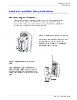
Figure 1 Attaching the Wall Mount Bracket...........................................................................14
Figure 2 Mount the Phone on the Wall Plate..........................................................................14
Figure 3 LCD in standby mode...............................................................................................16
Figure 4 LCD when a Call is Connected ................................................................................16
Figure 5 LCD display when Receiving a Call ........................................................................17
Tables in This Document
Table 1 Revision History .........................................................................................................6
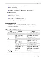
Table 2 Control Keys and Their Functions............................................................................11
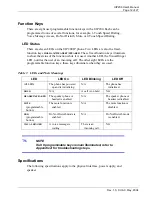
Table 3 LEDs and Their Meanings ........................................................................................12
Table 4 Fixed-Function Key and Programmable Key Defaults.............................................20
Table 5 Configuration Menus and Their Functions ...............................................................23


