Mounting and Set-up
PG-E-Series | Version 2.08
11
7
Mounting and Set-up
7.1 Unpacking
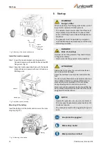
Step 1: Set the carton on the rigid, flat surface.
Step 2: Open the carton completely by cutting each cor-
ner from top to bottom.
Step 3: Leave the generator on carton to instal wheel kit.
Scope of delivery
- Wheels
- Handle
- Wheel axle
- Hardware bag; Including
1 - spark plug socket
1 - extension housing
- Instructions manual
7.2 Mounting
Mounting the wheels on:
- PG-E 30 SRA
- PG-E 40 SRA
- PG-E 60 SEA
- PG-E 80 TEA
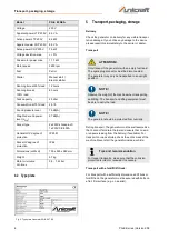
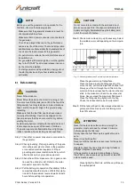
Step 1: Slide the axle through the frame brackets.
Step 2: Slide on the hub, wheel and flat washer, then in-
sert the cotter pin through the wheel axle hole.
Bend the cotter pin tabs outward to lock the pin
in place. (Fig. 7).
Mount the bumpers as shown in Fig. 7:
Step 3: Insert an M6 bolt through the rubber bumper and
insert an M8 bolt through the bottom of the bum-
per bracket. Secure the bolt with an M8 flange
nut.
Fig. 7: Mounting of the wheels and bumpers
Mounting the wheels on:
- PG-E 90 SEA
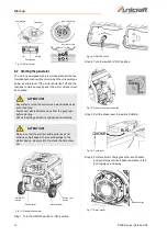
Step 1: Slide the axle through the frame brackets.
Step 1: Slide the axle through the frame brackets.
Step 2: Slide on the hub, wheel and flat washer
Step 3: Insert the cotter pin through the wheel axle hole.
Step 4: Bend the cotter pin tabs outward to lock the pin in
place.
Mount the bumpers as shown in Fig. 8:
Step 5: Insert an M6 bolt through the rubber bumper and
insert an M8 bolt through the bottom of the bum-
per bracket. Secure the bolt with an M8 flange
nut.
Step 6: Install an M8 bolt through the generator frame
and through top of the bumper bracket.
Step 7: Secure the bolt with an M8 flange nut.
Use protective gloves!
Wear safety boots!
Wear protective clothes!
CAUTION!
Risk of crushing!
Injuries to hands and fingers may result from
improper use of the generator.
- Note the weight of the generator. Ensure stable
supports and support devices.
Locknut
Support
Rubber pad
Flange
Summary of Contents for 6706030
Page 45: ...Notes PG E Series Version 2 08 45 14 Notes ...
Page 46: ...www unicraft de ...


