
Unibrain Fire-i 530/550/630/830/850 Operation Manual
Page 66
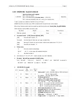
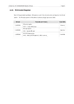
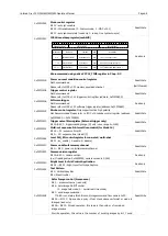
4.13.
PIO Control Register
Short for Programmable Input/Output, PIO provides a set of IO ports which can be configured by the defined
address. The PIO control register by 1394 address, for strobe and trigger signal, is as follows.
Address
Description (bit 0: msb)
Read/Write
0xF2F21000
PIO output register
Bit 30 : Strobe GPIO output
Write only
0xF2F21004
PIO input register
Bit 31 : trigger GPIO input
Read only
0xF2F21008
PIO GPIO enable register.
Bit 30 : Strobe pin GPIO selector (1: GPIO, 0: strobe)
Read/Write