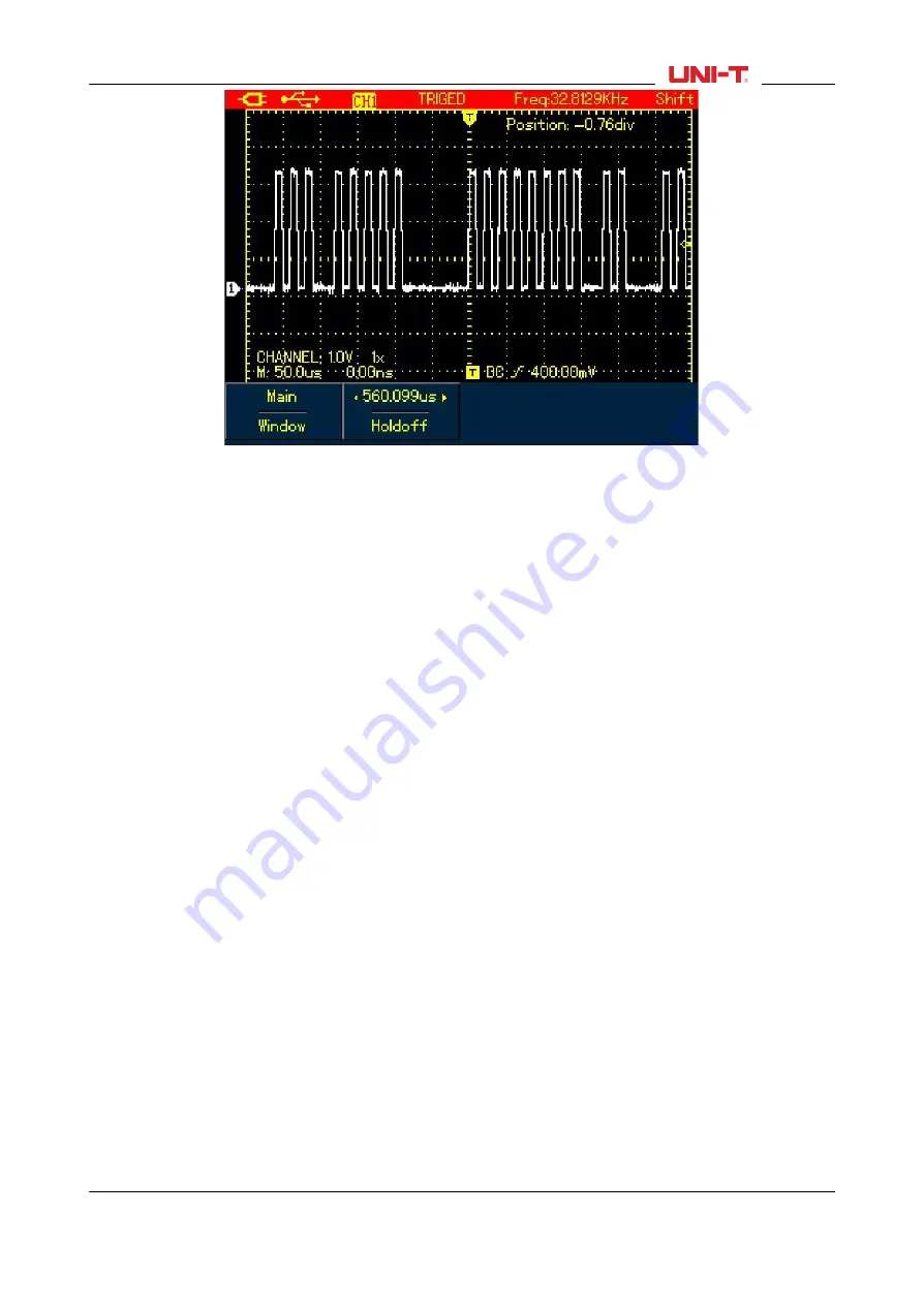
Figure 6-6 Trigger Hold-Off
Note:
1. The trigger hold-off time can be adjusted only when horizontal menu displays.
2. Generally hold-off time is a little smaller than “Big Period’, for instance for RS232 communication signal
waveform, hold-off time should be a little larger than start edge time of each frame in order to easily
observe the waveform.
6.4 Setting Trigger System
Trigger system determines when the Oscilloscope starts to acquire data and display waveforms. Once
the trigger is properly set, the Oscilloscope can transform unstable signal into meaningful waveform. When
the acquisition starts, the Oscilloscope continuously acquires enough data to fill the pretrigger portion that
is displayed to the left of trigger point. Then the trigger occurs, the Oscilloscope will continue to acquire
enough data to fill the posttrigger waveform to the right of trigger point. TRIGGER button is designed to set
up the Oscilloscope trigger functions.
TRIGGER: Trigger menu button
Trigger Level: to set up signal voltage that corresponds to the trigger point.
Press TRIGGER button to turn on trigger menu as indicated in the figure below, then press F1 button to
switch between different trigger types.
Press F2 to select trigger source.
UTD1000L User Manual
47


