background image

drive (Either 3.5" or 5.25").


7-8

IN:

Floppy secondary port address is 370-377

OUT: Floppy primary port address is 3F0-3F7.

9-10

IN:

Dual speed floppy drive support.

OUT: Single speed floppy drive.


11-12 IN:

Precompensation is fixed at 125ns for  all data rates.

OUT: Precompensation varies according to floppy  

data rates; 250, 300, and 500KHz data rates have 
250ns, 208ns, and 125ns precompensation each.

JP12

IN:

Hard disk secondary I/O port address is 170-77


OUT: Hard disk primary I/O port address is 1F0-1F7

JP17

IN:

Enable floppy controller.

OUT: Disable floppy controller.

JP20 1-2

IRQ15 select

2-3:

IRQ14 select

3.3  Cable Connection And System Integration

After the controller and the drives are properly configured, connect all the necessary
cables according to the following steps with the system powered off:

a. Connect the drive power to the system power supply.
b. Connect the 34 pin daisy chained flat cable from the drive to J5 connector

on the controller. The twisted end of the cable is connected to the first
drive. Make sure pin 1 of the cable is connected to pin 1 of the drive and
controller connectors.

c. Connect the 20 pin flat ribbon cable from the first drive to the J4 connector

on the controller.  Connect another 20 pin flat cable from the second drive
to J3 connector on the cable.

d. Connect the 34 pin daisy chained floppy flat cable to the J1 connector on

the controller. Connect the floppy drive power cable to the system power
supply.

e. Connect  the   drive  activity   LED  cable   from  the  system  panel   to  the   J6

connector on the controller board.

f. Remove the bracket from an empty  expansion slot and use the bracket

screw in step g.

Page 8

Reference Manual

Summary of Contents for ULTRA 12F24

Page 1: ...ULTRASTOR CORPORATION ULTRA 12F24 ESDI CONTROLLER INSTALLATION MANUAL REVISION A 4 1 92...

Page 2: ......

Page 3: ...nce Installation Appendix D Novell NetWare 386 Disk Duplexing Appendix E SCO UNIX Installation Guide for Two Controllers Appendix F Breaking the 528MB OS 2 Limitation and Duplexing under OS 2 LAN Mana...

Page 4: ...the fastest of AT buses available 16MHz It supports the largest selection of hard drives in the market today The ULTRA 12F24 also supports any mix 5 25 and 3 5 of up to three floppy disk drives or flo...

Page 5: ...ufacturer s instructions for setting jumpers Floppy Disk Drives Up to 3 floppy drives of any size with data rates from 125Kb s to 500Kb s with the manufacturer s instructions for setting jumpers Flopp...

Page 6: ...allation Finally you will have to know which operating system your PC will be using PC DOS or MS DOS OS 2 UNIX or Novell and which version of that operating system The ULTRA family of caching controll...

Page 7: ...f the control cable c Set the jumper to spin up the drive motor upon system power up rather than upon an ESDI spin up command generally the drive will come from the factory set to spin up upon power u...

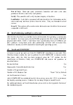
Page 8: ...Enable JP4 No Jumper BIOS Address C800 0 JP10 5 6 Floppy Configuration JP11 No Jumper Hard Disk Primary Address JP12 No Jumper Enable Floppy Controller JP17 Jumper IRQ14 15 Select JP20 2 3 Page 6 Refe...

Page 9: ...port JP11 Configure floppy controller 1 2 IN Support a third floppy drive with a single twisted cable The drive should be jumpered as DS4 OUT Support a third floppy drive with a double twisted cable T...

Page 10: ...cables according to the following steps with the system powered off a Connect the drive power to the system power supply b Connect the 34 pin daisy chained flat cable from the drive to J5 connector o...

Page 11: ...te to boot SETUP programs and AT ADVANCED DIAGNOSTIC programs are not required to add the ESDI drive to the system CMOS RAM However in system setup make sure that the hard drive is specified as instal...

Page 12: ...17 sector mapping is used for running any software that uses fixed 17 sectors per track The track mapping option is used for drives greater than 528MBytes under DOS All the options are independent of...

Page 13: ...changed Sector Mapping NO No Sector Mapping will be performed The disk s physical parameters will be used 17 17 Sector Mapping will be performed This is used to run any software which fixes the sector...

Page 14: ...d drive is over 1 2GB With this option the user will be able to use drives that are greater than 528MB without any third party software This cannot be used under Novell OS 2 or Unix Xenix operating sy...

Page 15: ...sers can also change the default value on interleave setup head skew and cylinder skew before executing the low level format g For most users go to the AUTOFORMAT field to low level format the specifi...

Page 16: ...ue shown is calculated and maximized according to the ESDI drives connected AutoFormat This option will perform automatic format procedure on the drive Four options are provided Brief Extended Brief N...

Page 17: ...list manually if so desired The defect list field allows the user to retrieve the defect list from the ESDI drive add a defect entry delete a grown defect entry store the manually entered grown defect...

Page 18: ...tion Using third party disk partitioning software will overcome this limitation Consult your DOS manual for installing the operating system 4 3 Novell and COMPSURF A feature to speed up and ease Novel...

Page 19: ...endor for the UltraStor 3rd floppy device driver EXFDRV SYS and see Appendix B Installing the 3rd Floppy Drive Tape Backup Unit Installation Please see Appendix B Installing the 3rd Floppy Drive Add O...

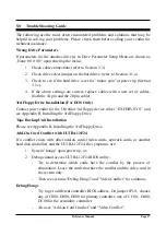
Page 20: ...gh level format Don t Achieve Full Capacity Under OS 2 1 1 1 2 for Drives Greater than 528MB To obtain the maximum drive capacity 528MB that OS 2 1 1 1 2 can support select 63 sector mapping and 1024...

Page 21: ...installation Make sure Track Mapping is disabled in UltraStor Drive Parameter Setup Menu Invalid Hard Disk Controller Failure Check jumper settings on the controller Reference Manual Page 19...

Page 22: ...This Page Left Intentionally Blank...

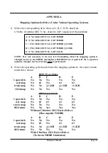
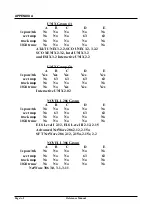
Page 23: ...ve choice DOS 3 3 or Above A B C D E 1 spare trk No No No No No sect map No 63 No 63 63 track map No No 1 2GB 1 2GB 1 2GB 1024 map No No No No No OS 2 1 1 1 2 1 3 A B C D E 1 spare trk No No No No No...

Page 24: ...3 63 63 63 track map No No No No No 1024 trunc No No Yes Yes Yes Interactive UNIX 2 02 NOVELL 286 Group A B C D E 1 spare trk No No No No No sect map No 63 No 63 63 track map No No No No No 1024 trunc...

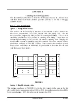
Page 25: ...Drives that are jumpered permanently to DS2 or DS1 for number counting from DS0 by the manufacturer cannot be installed using this method The cable needed for this installation is shown in FIGURE 1 b...

Page 26: ...and connect the power cable to the 3rd drive You may need a Y power cable if you have more than 4 drives hard disk and floppy combined in your system since most power supplies come with only 4 drive...

Page 27: ...rive 2 for 1 2MB drive 3 for 720KB drive 4 for 1 44MB drive DEVICE DRIVER SYS D 2 T aa S bb H 2 F cc where aa 40 for 360KB bb 9 for 360KB and 720KB 80 for all others 15 for 1 2M 18 for 1 44MB And wher...

Page 28: ...This Page Left Intentionally Blank...

Page 29: ...he PS 2 Model 30 286 floppy only configuration then the 12F 12F24 or 12C can connect up to 2 ESDI drives Operating systems that do not bypass the system BIOS INT13 call for disk operation such as DOS...

Page 30: ...ves o Refer to Section 4 1 Low Level Format Utility in the ULTRA Installation Guide After the low level drive preparation is done the drive s is ready for OS partitioning and formatting such as FDISK...

Page 31: ...e secondary port the system can support up to 4 ESDI drives operating under NetWare 386 Any pair of disk drives can be selected as a mirroring or duplexing pair as long as the drive pair capacity is c...

Page 32: ...990 Unlike the previous version 3 0 the new ISADISK DSK program changes the way drive parameters are derived for the secondary controller The secondary controller is no longer accessible if the primar...

Page 33: ...rom the backup copy b Load the ISADISK DSK file with the DOS Debug program by typing debug ISADISK DSK f c Once the debug program s prompt sign appears search for the hexadecimal data 3D 00 F0 by typi...

Page 34: ...Novell Server program Following the prompt enter the following commands to load the hard disk device driver for primary and secondary controller card LOAD ISADISK l I O port 1F0 Interrupt number E LOA...

Page 35: ...troller There should be 0s0 and 1s0 devices existing in the dev rdsk directory The mkdev that will be used to create device will create 2s0 and 3s0 for first and second drive in the secondary controll...

Page 36: ...dkinit only refers to 2s0 as the first drive in the secondary controller and 3s0 as the secondary drive in the secondary controller If the device created is not 2s0 or 3s0 a problem will occur during...

Page 37: ...acturing defect map The following procedures for creating UNIX partition scanning disk creating filesystem are the same as the regular procedures for adding the 2nd drive in the primary controller Ple...

Page 38: ...This Page Left Intentionally Blank...

Page 39: ...reseen problems occur contact the OEM suppling OS 2 While the UltraStor s OS 2 device driver supports the ULTRA BIOS track mapping mode for large drives this feature will not be supported under OS 2 r...

Page 40: ...llation guide Procedures for OS 2 Release 1 2 with 3 5 diskette 1 IMPORTANT Back up the original OS 2 Install diskette and use the backup copy of the Install diskette for the following steps 2 Copy OS...

Page 41: ...After completing the OS 2 installation you may want to restore the Installation diskette by deleting disk01 sys and restoring all the RC and FDISK COM from the temporary diskette Please refer to OS 2...

Page 42: ...een and type A SETUP and press the return key 4 Proceed with the installation until the Install LAN Manager menu appears and then select the Server option Refer to the LAN Manager documentation for a...

Page 43: ...lation Procedure for Novell NetWare 286 AN001 Head and Cylinder Skew Calculation AN004 Automatic Drive Preparation Utility UFORMAT Command AN006 ESDI Drives for Use with UltraStor Controllers AN012 Du...

Page 44: ...This Page Left Intentionally Blank...

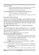
Page 45: ...rs 3 Follow Section 4 1 1 Page 10 for BIOS setup to both controllers and set the mapping mode for all the drives as below The Mapping Mode for all drives is as follows One Spare Sector Trk NO Sector M...

Page 46: ...This Page Left Intentionally Blank...

Page 47: ...card the following jumpers should be set as below JP10 1 2 OUT BIOS address at CC00 0 3 4 IN 5 6 OUT JP12 IN Hard disk secondary I O port address 170 177 376 377 JP17 OUT Disable floppy controller JP...

Page 48: ...This Page Left Intentionally Blank...

Page 49: ...NOTES...

Page 50: ...guarantee that interference will not occur in a particular installation If this equipment does cause harmful interference to radio or television reception which can be determined by turning the equip...

Page 51: ...LTRASTOR Corporation reserves the right to change specifications at any time without notice IBM and AT are registered trademarks of International Business Machines Corporation MSDOS is a registered tr...

Page 52: ...ULTRASTOR CORPORATION...

Reviews: