


Chapter 7: Field Service Components
00.053.101, Revision C SonixMDP/SP/OP Service Manual
7-34
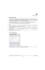
3.
Connect the PCI cables as below.
4.
Connect the multi-colored and black power cables to connectors 3 and 4.
5.
Connect the CAT5 cable to the CAT5 connector (
5
) on the top, right-hand side of the front block/ultrasound
module.
Note:
The ribbon cables coming from the PCI card are connected in reverse. The top cable from the PCI card
(
1
) is connected to the bottom PCI connector on the front block/ultrasound module (
1
). Consequently, the
bottom cable from the PCI card (
2
) is connected to the top PCI connector on the front block/ultrasound
module (
2
).
Note:
The order in which these cables are connected does not matter.
1
2
1
2
3
4
5
Summary of Contents for SonixMDP
Page 1: ...SonixMDP SP OP Ultrasound System Service Manual...
Page 2: ......
Page 4: ......
Page 10: ...Table of Contents 00 053 101 Revision C SonixMDP SP OP Service Manual vi...
Page 12: ...List of Service Drawings 00 053 101 Revision C SonixMDP SP OP Service Manual ii...
Page 44: ...Chapter 4 Performance Testing 00 053 101 Revision C SonixMDP SP OP Service Manual 4 4...
Page 48: ...Chapter 5 Software 00 053 101 Revision C SonixMDP SP OP Service Manual 5 4...
Page 124: ...Chapter 9 Network Configuration 00 053 101 Revision C SonixMDP SP OP Service Manual 9 8...
Page 142: ...Chapter 11 Maintenance 00 053 101 Revision C SonixMDP SP OP Service Manual 11 16...
Page 150: ...Chapter 12 Troubleshooting Issues 00 053 101 Revision C SonixMDP SP OP Service Manual 12 8...
Page 166: ...Appendix C Ultrasonix Limited Warranty 00 053 101 Revision C SonixMDP SP OP Service Manual C 2...
Page 168: ...Appendix D Service Drawings 00 053 101 Revision C SonixMDP SP OP Service Manual D 2...


