background image

Property of Ultrasonic Power Corporation - © 2019 
Publication # 190610


Sonic Touch II® (PPC30) User Manual 


Ultrasonic Power Corporation 

239 E. Stephenson Street 

Freeport, IL 61032, U.S.A. 

Phone: 815-235-

6020 • 1-800-575-0168 

Fax: 815-232-2150 


Email: 

[email protected]


www.upcorp.com


Summary of Contents for PPC30

Page 1: ...rporation 2019 Publication 190610 Sonic Touch II PPC30 User Manual Ultrasonic Power Corporation 239 E Stephenson Street Freeport IL 61032 U S A Phone 815 235 6020 1 800 575 0168 Fax 815 232 2150 Email sonic upcorp com www upcorp com ...

Page 2: ...l aspects of the system configuration prior to start up We know that your Ultrasonic Power Corporation cleaning system will serve you for years to come Thank You again for selecting Ultrasonic Power Corporation for your cleaning needs Sincerely The Ultrasonic Power Family Please read the entire manual The console series of cleaning systems require special care for proper operation This manual give...

Page 3: ...er Login 14 8 Setup 16 9 Alarms 17 10 Alarm history 19 11 Frequency Display 20 12 Power Output Display 21 13 Ultrasonics Configuration 22 14 Heat Configuration 28 15 Pump Configuration Optional 34 16 Skimmer Configuration Optional 40 17 LCS Liquid Condition Sensor 46 18 Machine Stats 49 19 USB Log 50 20 Diagnostics System Diagnostics Manager 52 21 Diagnostics System Dump Instructions 53 22 Warrant...

Page 4: ...damage injury and or death High Voltage Proper Voltage Failure to comply with this safety statement may result in equipment damage injury and or death Caution Moving Parts Failure to comply with this safety statement may result in equipment damage injury and or death Electrostatic Sensitive Devices ESD Failure to comply with this safety statement may result in equipment damage ...

Page 5: ... 2 W Max Without USB Interface Reverse Polarity Protection Dimensions W x H x D 7 8 in x 5 5 in x 2 in Weight 1 433 lbs IF 1 USB 2 0 Type A 0 49 A IF 2 USB 2 0 Type A 0 49 A IF 3 Ethernet 1x RJ45 shielded IF 4 CAN bus 3 pins of the 6 pin multipoint connector Display Type Color TFT Display Size 7 Colors 16 7 M Resolution WVGA 800 x 480 pixels Analog Resistive Other IP65 protection front side IP20 p...

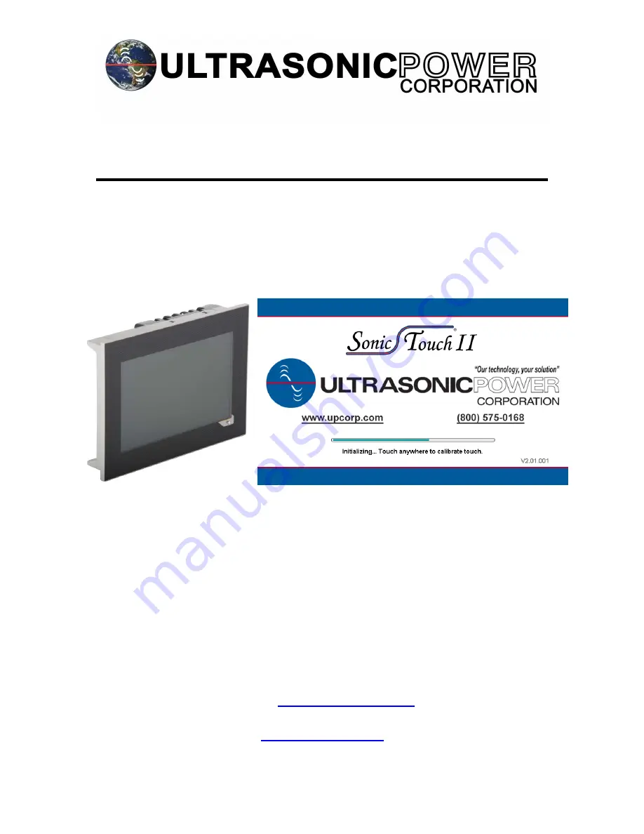
Page 6: ... care Wear grounding strap and or properly rated footwear Upon power up of the system the panel will cycle through the loading screen as seen in the image At this time you may choose to calibrate touch controls Otherwise there is an alternative location to perform touch calibration which will be exposed in another section of this document ...

Page 7: ...IBRATION The touch calibration page allows the user to increase the touch control accuracy should it fall out of calibration To calibrate touch control press the visible target with your finger A second target will appear Repeat the process until the panel is finished calibrating ...

Page 8: ...s the home screen for the Sonic Touch II This page allows the user start stop control for configured peripherals ultrasonic intensity control frequency sweep control temperature control and displays alarm information These features will be examined in further detail later in this document ...

Page 9: ...nic Power Corporation 2019 Publication 190610 6 BASIC NAVIGATION CONTROL Every page contains these common features navigation button 1 home button 2 user login button 3 back button 4 and an error refresh button 5 1 2 5 3 4 ...

Page 10: ...ty of Ultrasonic Power Corporation 2019 Publication 190610 Pressing the back button reverts the user to the previous page if any Pressing the home button from any other page will direct the user to the home page ...

Page 11: ...orporation 2019 Publication 190610 The error refresh button clears addressed errors alarms This button will only function if the errors alarms have been corrected Errors alarms will be examined in further detail later in this document ...

Page 12: ... the user to view the options accessible at the current permissions level The figure below displays the options available at the Supervisor permission level Not all of these features are available in the Operator permission level Each of these features will be examined in further detail later in this document ...

Page 13: ...on 2019 Publication 190610 Pressing the user login shortcut will direct the user to the login page The figure below displays the user login page Information regarding login information will be examined in further detail later in this document ...

Page 14: ...upervisor permission allows full access to all features and capabilities including those of Operator permission The user login page displays from top to bottom password entry logout button the current permission access level and the time remaining before the system will automatically revert the user to Operator permissions To log out of Supervisor permissions one of three methods may be used 1 Pre...

Page 15: ...ad will display ready to accept the password once entered Upon entering the desired password press the enter return button in the bottom right corner of the keypad _ _ _ _ _ _ _ _ _ _ _ _ _ _ _ _ _ _ _ _ _ _ _ _ _ _ _ _ _ _ _ _ _ _ _ _ _ _ _ _ _ _ _ _ _ _ User login passwords are as follows Operator 0 Supervisor 4517 Upon access to each level the user login shortcut image will adjust accordingly ...

Page 16: ...ter Mode may be toggled on in order to disable low liquid level protection for the usage of high quality DI water This mode is only for usage if the system is otherwise incapable of running due to an inability for the equipped sensor to detect this DI water If you wish to maintain low liquid level protection whilst using high quality DI water please contact your UPC representative for alternative ...

Page 17: ...e bottom of every page and in the alarm page itself Potentially common active errors alarms include not limited to 1 Output Power Error This error occurs if one or more outputs experiences an issue 2 Low Liquid Error This error occurs if the liquid level in the unit does not meet minimum requirements 3 Temperature Watchdog Error This error occurs if the liquid temperature in the unit does increase...

Page 18: ... button If multiple alarms are active they can be viewed form the alarms page Up down arrows are used to navigate through the alarms and the alarms page contains and additional error refresh button located center on the right side Alarms can only be cleared if the issue is corrected Actual alarm codes will be examined in further detail later in this document ...

Page 19: ... Property of Ultrasonic Power Corporation 2019 Publication 190610 10 ALARM HISTORY The alarm history page allows the user to view past active alarms Up down arrows are used to navigate through the alarms ...

Page 20: ... Caution Ensure tank contains the minumum required amount of liquid prior to operation Warning Ensure proper drainage or liquid removal is installed prior to operation The values displayed here are means to verify the performance of the system within a degree of tolerance As the ultrasonic wattage is increased configured by the manufacturer more numeric windows are displayed to accommodate the sys...

Page 21: ...ional location to adjust power intensity Caution Ensure tank contains the minumum required amount of liquid prior to operation Warning Ensure proper drainage or liquid removal is installed prior to operation The values displayed are means to verify the performance of the system within a degree of tolerance As the ultrasonic wattage is increased configured by the manufacturer more numeric windows a...

Page 22: ...lows the user to operate the peripheral directly from the home screen 2 Timer Countdown allows the peripheral to operate for a predetermined amount of time 9 59 59 maximum 3 Schedule 7 Day Timer allows the peripheral to operate via a 7 day timer programmed by the user Caution Ensure tank contains the minumum required amount of liquid prior to operation Warning Ensure proper drainage or liquid remo...

Page 23: ...23 Property of Ultrasonic Power Corporation 2019 Publication 190610 The currently set mode is displayed below the ...

Page 24: ...10 This configuration page may be accessed by pressing the on the main page or via the navigation window To cycle between operation modes press the dial once with your finger Each time the dial is pressed the system will index through each mode in a single direction ...

Page 25: ...Power Corporation 2019 Publication 190610 In manual mode the user may enable the peripheral by pressing in either of the two locations highlighted in red The Run button starts the peripheral The Reset button stops the peripheral ...

Page 26: ...n red The time may be entered via the up down arrows or by pressing the numeric windows The Run button starts the peripheral The Reset button stops the peripheral and resets the time to the value previously entered Pressing this button again clears the timer The time value may be increased decreased at any time whether the peripheral is enabled or disabled ...

Page 27: ...er location highlighted in red Start and stop times may be entered via the up down arrows or by pressing the numeric windows The day to be programmed is changed via the drop down window If a day is to be disabled set the start and stop times equal to each other This is easily done via the Now buttons Wednesday Enabled Wednesday Disabled ...

Page 28: ...e user to operate the peripheral directly from the home screen 2 Timer Countdown allows the peripheral to operate for a predetermined amount of time 9 59 59 maximum 3 Schedule 7 Day Timer allows the peripheral to operate via a 7 day timer programmed by the user Caution Ensure tank contains the minumum required amount of liquid prior to operation Warning Ensure proper drainage or liquid removal is ...

Page 29: ...29 Property of Ultrasonic Power Corporation 2019 Publication 190610 The currently set mode is displayed below the ...

Page 30: ...10 This configuration page may be accessed by pressing the on the main page or via the navigation window To cycle between operation modes press the dial once with your finger Each time the dial is pressed the system will index through each mode in a single direction ...

Page 31: ...Power Corporation 2019 Publication 190610 In manual mode the user may enable the peripheral by pressing in either of the two locations highlighted in red The Run button starts the peripheral The Reset button stops the peripheral ...

Page 32: ...n red The time may be entered via the up down arrows or by pressing the numeric windows The Run button starts the peripheral The Reset button stops the peripheral and resets the time to the value previously entered Pressing this button again clears the value The time value may be increased decreased at any time whether the peripheral is enabled or disabled ...

Page 33: ...ther location highlighted in red Start and stop times may be entered via the up down arrows or by pressing the numeric windows The day to be programmed is changed via the drop down window If a day is to be disabled set the start and stop times equal to each other This is easily done via the Now buttons Tuesday Enabled Tuesday Disabled ...

Page 34: ...ws the user to operate the peripheral directly from the home screen 2 Timer Countdown allows the peripheral to operate for a predetermined amount of time 9 59 59 maximum 3 Schedule 7 Day Timer allows the peripheral to operate via a 7 day timer programmed by the user Caution Ensure tank contains the minumum required amount of liquid prior to operation Warning Ensure proper drainage or liquid remova...

Page 35: ...35 Property of Ultrasonic Power Corporation 2019 Publication 190610 The currently set mode is displayed below the ...

Page 36: ...rmation and pump system the liquid will fall below the Low Liquid Level sensor and trigger an error By holding this button the user is capable of running the pump even while this error is in effect This configuration page may be accessed by pressing the on the main page or via the navigation window To cycle between operation modes press the dial once with your finger Each time the dial is pressed ...

Page 37: ...37 Property of Ultrasonic Power Corporation 2019 Publication 190610 In manual mode the user may enable the peripheral by pressing in either of the two locations highlighted in red ...

Page 38: ...rasonic Power Corporation 2019 Publication 190610 The Run button starts the peripheral The Reset button stops the peripheral In Timer mode the user may input the time value by pressing either location highlighted in red ...

Page 39: ...utton starts the peripheral The Reset button stops the peripheral and resets the time to the value previously entered Pressing this button again clears the value The time value may be increased decreased at any time whether the peripheral is enabled or disabled In Schedule mode the user may input start stop times by pressing either location highlighted in red ...

Page 40: ...via the up down arrows or by pressing the numeric windows The day to be programmed is changed via the drop down window If a day is to be disabled set the start and stop times equal to each other This is easily done via the Now buttons 16 SKIMMER CONFIGURATION OPTIONAL Wednesday Enabled Wednesday Disabled ...

Page 41: ... directly from the home screen 2 Timer Countdown allows the peripheral to operate for a predetermined amount of time 9 59 59 maximum 3 Schedule 7 Day Timer allows the peripheral to operate via a 7 day timer programmed by the user Caution Ensure tank contains the minumum required amount of liquid prior to operation Warning Ensure proper drainage or liquid removal is installed prior to operation The...

Page 42: ...y of Ultrasonic Power Corporation 2019 Publication 190610 This configuration page may be accessed by pressing the on the main page or via the navigation window To cycle between operation modes press the dial once ...

Page 43: ... 2019 Publication 190610 with your finger Each time the dial is pressed the system will index through each mode in a single direction In manual mode the user may enable the peripheral by pressing in either of the two locations highlighted in red ...

Page 44: ...rasonic Power Corporation 2019 Publication 190610 The Run button starts the peripheral The Reset button stops the peripheral In Timer mode the user may input the time value by pressing either location highlighted in red ...

Page 45: ...utton starts the peripheral The Reset button stops the peripheral and resets the time to the value previously entered Pressing this button again clears the value The time value may be increased decreased at any time whether the peripheral is enabled or disabled In Schedule mode the user may input start stop times by pressing either location highlighted in red ...

Page 46: ...d via the up down arrows or by pressing the numeric windows The day to be programmed is changed via the drop down window If a day is to be disabled set the start and stop times equal to each other This is easily done via the Now buttons 17 LCS LIQUID CONDITION SENSOR Wednesday Enabled Wednesday Disabled ...

Page 47: ...ithin the working volume of the tank Intensity and sweep controls are located on this page for convenience while attempting to optimize performance within the tank Caution Ensure tank contains the minumum required amount of liquid prior to operation Warning Ensure proper drainage or liquid removal is installed prior to operation ...

Page 48: ...formance levels inside the tank Variables include but are not limited to 1 Power intensity 2 Frequency sweep 3 Water Composition 4 Liquid Level Temperature 5 Surfactant Solution Ratio 6 Containment Boundaries 7 Part Density Geometry Data pertaining to acoustic levels and settings may be tracked for up to ten minutes before the trend lines refresh Variables displayed on the page are color coded to ...

Page 49: ...on 190610 18 MACHINE STATS The machine stats page allows the user to view elapsed time meter for multiple components of the system The filter elapsed time meter holds the ability to be reset This feature is intended to aid in routine maintenance and scheduling ...

Page 50: ...og page allows the user to download recorded data onto a flash drive FAT32 format at least 1 GB This is a list of parameters that the system records whenever the ultrasonics are on 1 Timestamp 2 LCS 3 Power intensity 4 Frequency sweep 5 Last loaded recipe 6 Output power 7 Output Frequency ...

Page 51: ...ad information will be made visible The USB device is automatically ejected following a download Downloaded information may be viewed as a spreadsheet using Microsoft Excel The save interval of the data logging feature is three minutes If the ultrasonics are on longer than three minutes information will span multiple files ...

Page 52: ...the SDM includes 1 System information 2 Software information 3 Hardware information 4 Motion information 5 Logger information 6 Profiler information 7 System dump feature The SDM houses the System Dump feature which stores all current information to the system on a device which may then be sent out for diagnostics and troubleshooting The figure below displays the SDM with the orange system dump fe...

Page 53: ... 2019 Publication 190610 21 DIAGNOSTICS SYSTEM DUMP INSTRUCTIONS Insert a USB or other device into the USB port and look to the USB Log Backup page Once the system recognizes the device alternate options become visible Press the Link USB option ...

Page 54: ...54 Property of Ultrasonic Power Corporation 2019 Publication 190610 Redirect to the SDM found in the diagnostics page Select the orange System Dump tile Select a system dump option ...

Page 55: ...ion 2019 Publication 190610 Confirm the system dump option selection Allow the system 10 15 seconds for the system dump to take place The loading bar will remain at 0 for the entirety of this operation Then select the Abort System Dump option ...

Page 56: ...56 Property of Ultrasonic Power Corporation 2019 Publication 190610 Confirm the abort selection At this point the page should state that the system dump is already completed Select continue ...

Page 57: ...k to the SDM page Again select the orange System Dump tile At this point the user will have the option to perform another system dump in which case the previous steps are repeated by selecting Ok Otherwise verify the timestamp and select the Save button to continue the previously saved system dump ...

Page 58: ...ly save to a USB or another external device The other folders located in this page house internal data pertinent to the system The figure below displays a USB flash drive as MY_USB this name may not always be the same Select the folder belonging to the USB Warning Saving files to incorrect locations may cause internal malfunctions of the system ...

Page 59: ... 2019 Publication 190610 Once the folder is selected files stored in the device will be displayed In this case a previously stored system dump and data logging files exist Press the disk image or Save button to save the system dump to the device ...

Page 60: ... Power Corporation 2019 Publication 190610 Upon a successful download press Continue Revert to the USB Log Backup page and press Eject USB The USB flash drive may then be uninstalled for further troubleshooting and diagnostics ...

Page 61: ...or Customer if the first Purchaser is a distributor only and is not otherwise transferable without the prior written consent of UPC THIRD PARTY COMPONENT WARRANTY Concerning any products and components not manufactured by UPC Third Party Products but used in the manufacture of the final UPC Product UPC agrees to transfer all warranties given by the manufacturer of the Third Party Products each a T...

Page 62: ...or component which has been i incorrectly operated or misused ex operating the equipment dry dropping heavy objects into the cleaning tank incorrect voltage connections ii altered or iii modified d expendable items such as fuses bulbs or similar parts incorporated in a Product having a useful life inherently shorter than twelve 12 months e damage from intentional acts fire acts of God hurricanes t...

Page 63: ...gardless of any other agreement between the first Purchaser or Customer if the first Purchaser is a distributor and UPC this Warranty will be governed and controlled in all respects by the laws of the State of Illinois USA including interpretation enforceability validity and construction without regard to any conflict of law provisions The sole proper venue for the resolution of any disputes arisi...

Page 64: ...if the first Purchaser is a distributor place of business using a transportation method of its choosing or through consultation with the first Purchaser or Customer if the first Purchaser is a distributor All Products and accessories must be shipped in their original shipping containers or other solid and durable shipping container Failure to return the Product or accessories to UPC or to follow t...

Page 65: ...ty Policy All warranty repairs are subject to an initial inspection and approval by an authorized UPC repair representative to determine if the requested repairs are covered by an applicable UPC Warranty Policy If a repair is NOT covered under warranty UPC will issue a quote for the cost of the repairs needed and will provide a stated reason for the non warranty coverage determination As indicated...

Page 66: ... in the Pricing Schedule Shipping Expenses Abandoned Product Failure to Authorize Repair in Timely Manner Shipping expenses are the responsibility of the customer UPC recommends a shipping method which provides for tracking of returned product and also includes insurance against shipping damage and or property loss UPC will not be responsible for damaged and or lost product prior to receipt by UPC...

Page 67: ... equipment must be completed UPC reserves the right to refuse acceptance of equipment A 95 hour Cleaning Fee will be assessed for the cleaning of equipment that is considered by UPC to be excessively dirty unclean OEM Warranty Replacement Repair Policy All service requests from customers of OEMs must originate their service request through the OEM It is the OEM s responsibility to obtain a valid U...

Page 68: ...dicated above all product returns for service must have a RMA number prior to shipment to UPC Product without an RMA number will be refused Please ship with shipment costs pre paid to Ultrasonic Power Corporation Attn RMA Coordinator 239 East Stephenson Street Freeport Illinois 61032 USA 1 800 575 0168 1 815 235 6020 ...

Page 69: ...t Evaluation Fee 145 00 Waived with warranty replacement due to defect NON Warranty 600 00 Expired warranty equipment malfunction customer damage Repair Rates for Immersible Transducers Comments Warranty Repair 0 00 UPC Warranty Applies Test Evaluation Fee 150 00 Waived with warranty replacement due to defect NON Warranty Quote Expired warranty equipment malfunction customer damage Repair Rates fo...

Page 70: ...ems Comments Warranty Repair 0 00 UPC Warranty Applies Test Evaluation Fee 300 00 Waived with warranty replacement due to defect NON Warranty Quote Expired warranty equipment malfunction customer damage Cleaning Fee 95 hour Additional Cleaning Fee to be assessed based on judgment of RMA Coordinator ...

Page 71: ...y of Ultrasonic Power Corporation 2019 Publication 190610 From RMA Ship To Ultrasonic Power Corporation 239 East Stephenson Street Freeport IL 61032 Attention RMA Coordinator cut here FRAGILE ELECTRONIC EQUIPMENT ...

Page 72: ...72 Property of Ultrasonic Power Corporation 2019 Publication 190610 Please contact your Ultrasonic Power Corporation representative with any question regarding your Ultrasonic cleaning system ...

Reviews: