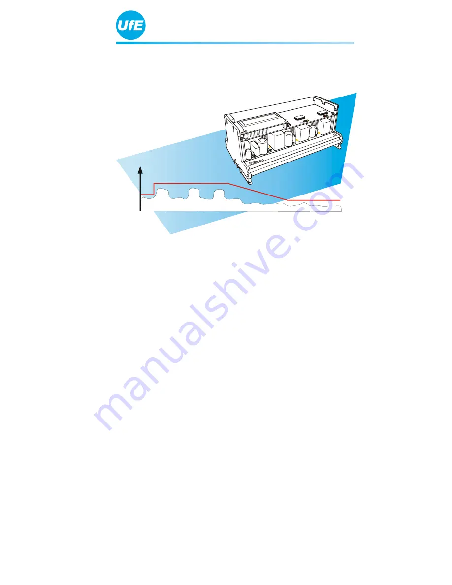
ENS31 Automatic Isolation Unit
Product Description
Issue 09/2005
Page 1: ...ENS31 Automatic Isolation Unit Product Description Issue 09 2005...
Page 2: ...the documentation Copyright This Product Description is the copyright of UfE GmbH This manual is intended for the customers and project planner It contains instructions and information which must not...
Page 3: ...impedance measurement process 10 3 7 Automatic calibration of the impedance measurement 11 3 8 Automatic adaptation of switching thresholds to the mains power conditions 12 3 9 Automatic synchronisati...
Page 4: ...ding systems It prevents uncontrolled island effects following failure or shutdown of the public electricity supply The ENS31 complies with DIN VDE 0126 1 1 and is approved as a sub stitute for manual...
Page 5: ...lays Rel1 and Rel2 Request for the switching status of the external contactors occurs via two acknowledge ment inputs After switching on Contactor 1 is activated first and Contactor 2 is only enabled...
Page 6: ...d on the front side of the ENS31 X XXXXX A B C D A LCD The unit and mains power status is shown on a 2 line LC display Each line can display 16 characters B to D LEDs In addition to the LCD the unit a...
Page 7: ...op edge of the ENS31 R E L A I S 1 2 3 4 KONTAKTE 1 2 N E T Z N L1 L2 L3 A B C A 4 connection terminals for contactor control potential free B 2 connection terminals to connect positively driven auxil...
Page 8: ...efault settings can be changed if necessary The ENS manufac turer must be informed of these requirements however prior to con figuration 3 2 Fluctuations in the mains power supply The threshold values...
Page 9: ...30 degrees the feeding point is disconnected from the power supply If the rate of change of the frequency RoCoF exceeds 1 Hz s discon nection from the supply is also triggered 3 4 Impedance jumps All...
Page 10: ...ntegrated in the ENS31 optimised impedance measurement process automatic calibration of the measured impedance change automatic adaptation of switching thresholds to frequent fluctuations and interfer...
Page 11: ...esistor in the ENS performs an automatic continuous cali bration of the impedance measurements and at the same time a continu ous automatic self test Manual calibration is no longer necessary To compl...
Page 12: ...ed to a less sensitive value the ENS31 switches off briefly in order to check whether the power supply is still available The threshold is only changed to a less sensitive value when it is recognised...
Page 13: ...tronger test signal through synchronisation This enables even higher measuring accuracy Faulty triggering is practically zero and operation is more stable The parallel connected ENS units generate a d...
Page 14: ...1 isolation unit is in a perfect condition 4 1 2 Conditions for installation The ENS31 is intended for installation on a top hat rail in an electrical cabinet or in a meter cabinet It cannot be instal...
Page 15: ...tion position of the ENS31 so that you can see the ENS31 and its indicators LCD and LEDs without opening the cabinet The cut out must have the following dimensions X XXXXX 219 mm 74 mm 4 1 4 Mounting...
Page 16: ...r generator is only connected to the mains via the two switching elements assigned to the ENS Risk of accident The ENS31 must be protected by pre fuses in the mains feed circuit min 6 A max 25 A Obser...
Page 17: ...not conducting electricity Switch the power generator feeder ENS31 and contactors as follows FEEDER UfE ENS31 R1R2R3R4 RELAY K1 N L1 L2 L3 MAINS L1 L2 L3 N MAINS min 6 A max 25 A 21 22 K10 1 K10 1 4...
Page 18: ...ways bypass the unit The neutral con ductor MUST be connected to the ENS31 otherwise the unit may be damaged If the ENS31 is switched on and off by means of a system control unit the L1 connection of...
Page 19: ...calibration of the impedance measurement continuous automatic self test of the isolation unit replaces the isolation unit provided by the public electricity supplier which must be permanently accessi...
Page 20: ...10 to 90 relative humidity non condensating Nominal current of power feeder According to max switching power of the contactors The unit disconnects the mains under the following defined condi tions c...