


UDO Super 6 — Owner’s Manual
85
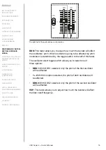
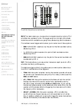
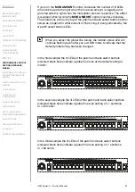
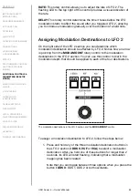
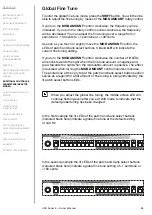
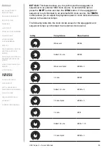
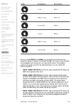
2. Whilst holding down one of the modulation destination buttons,
turn the
MOD AMOUNT
rotary control to dial in the amount of
modulation you would like to apply. You can adjust the modulation
amount over a range from -100% (negative modulation amounts) to
+100% (positive modulation amounts). The LEDs of the patch and
bank select buttons
1
-
8
and
A
-
H
will indicate your setting.
If you turn the
MOD AMOUNT
control clockwise the number of
lit LEDs will shrink towards the right when the modulation amount is
negative and grow towards the right when the modulation amount
is positive. The effect is reversed when turning the MOD AMOUNT
control counter-clockwise. The printed line at the very top of the
patch and bank select button section serves as a legend for the
amount value indicated by the buttons’ LEDs.
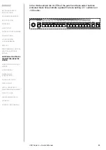
3. Release the modulation destination button. Its LED will become
solidly lit.
You can also use the modulation matrix to assign more modulation
destinations to be controlled by LFO 2. See pages 90-95 for more
details on how to use the modulation matrix.
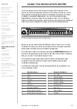
The three modulation destination buttons don’t only allow you to create
modulation mappings. You can also use them to instantly determine
whether a modulation destination should be affected by LFO 2 or not.
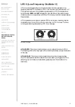
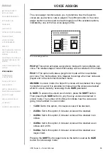
I DDS II:
This button allows you to determine which oscillator is going to
be affected by LFO 2 modulation as set by the LFO 2 rotary controls and
the modulation routings. You can toggle between the following options:
• I: With DDS 1 selected (left LED solidly lit), only the pitch of the first
oscillator will be affected.
• II:
With DDS 2 selected (right LED solidly lit), only the pitch of the
second oscillator will be affected.
• I + II:
With this option selected (both LEDs solidly lit), the pitch of both
oscillators will be affected.
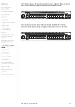
VCF: This button allows you to determine whether the filter cutoff
frequency is going to be affected by LFO 2 modulation as set by the LFO 2
rotary controls and the modulation routings.
VCA:
This button allows you to determine whether the VCA level is going
to be affected by LFO 2 modulation as set by the LFO 2 rotary controls
and the modulation routings.
You may also toggle the single modulation destination buttons on and
off during your playing to modify the impact of LFO 2 in real-time.
Summary of Contents for SUPER 6
Page 142: ......