
SARA-G450 - System integration manual
UBX-18046432 - R08
Design-in
Page 75 of 143
C1-Public
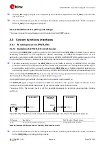
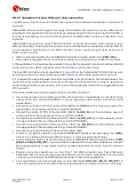
2.4
Antenna interface
The ANT pin, provided by all the SARA-G450 modules, represents the RF input/output used to
transmit and receive the 2G RF cellular signals: the antenna must be connected to this pin. The ANT
pin has a nominal characteristic impedance of 50
and must be connected to the antenna through a
50
transmission line to allow transmission and reception of radio frequency (RF) signals in the 2G
operating bands.
2.4.1
Antenna RF interface (ANT)
2.4.1.1
General guidelines for antenna selection and design
The cellular antenna is the most critical component to be evaluated: care must be taken about it at
the start of the design development, when the physical dimensions of the application board are under
analysis/decision, since the RF compliance of the device integrating a SARA-G450 module with all the
applicable required certification schemes depends from antenna radiating performance.
Cellular antennas are typically available as:
External antenna (e.g. linear monopole):
o
External antenna usage basically does not imply physical restrictions on the design of the PCB
where the SARA-G450 module is mounted.
o
The radiation performance mainly depends on the antenna: select the antenna with optimal
radiating performance in the operating bands.
o
If antenna detection functionality is required, select an antenna assembly provided with an
appropriate built-in diagnostic circuit with a resistor connected to GND: see guidelines in
section
o
Select an RF cable with minimum insertion loss: additional insertion loss due to low quality or
long cable reduces radiation performance.
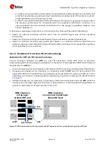
o
Select a suitable 50
connector providing clean PCB-to-RF-cable transition: it is
recommended to strictly follow the layout and cable termination guidelines provided by the
connector manufacturer.
Integrated antenna (PCB antennas such as patches or ceramic SMT elements):
o
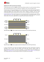
Internal integrated antenna implies physical restriction to the design of the PCB: the ground
plane can be reduced down to a minimum size that must be similar to the quarter of the
wavelength of the minimum frequency that has to be radiated. As numerical example:
Frequency = 824 MHz
Wavelength = 36.4 cm
Minimum ground plane size = 9.1 cm
o
The radiation performance depends on the whole PCB and antenna system design, including
product mechanical design and usage: select the antenna with optimal radiating performance
in the operating bands according to the mechanical specifications of the PCB and the whole
product.
o
Select a complete custom antenna designed by an antenna manufacturer if the required
ground plane dimensions are very small (e.g. less than 6.5 cm long and 4 cm wide): the antenna
design process should begin at the start of the whole product design process.
o
Select an integrated antenna solution provided by an antenna manufacturer if the required
ground plane dimensions are large enough according to the related integrated antenna
solution specifications: the antenna selection and the definition of its placement in the product
layout should begin at the start of the product design process.


