


ODIN-W2 series - System integration manual
UBX-14040040 - R20
System description
Page 10 of 43
C1-Public
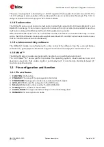
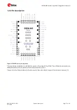
1.2.2
Pin description
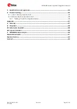
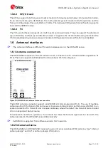
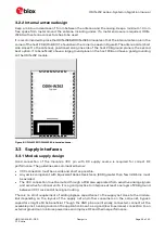
Figure 2: ODIN-W2 series pin assignment
The signals are available on castellation pads on the edge of the PCB. The unfilled circular pads are
GND pads. Black circular pads are test and production points.
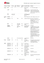
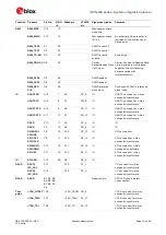
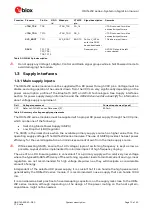
The pin id in the Table 2 refers to the ids used in the
u-blox Short range AT commands manual [1].