
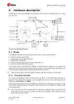


BMD-34 / 38 EVK - User guide
UBX-19033356 - R06
Hardware description
Page 11 of 20
C1-Public
Figure 9: NFC connector
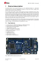
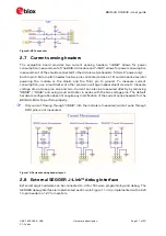
2.7
Current sensing headers
The evaluation board provides two current sensing headers.
“
JBMD
”
allows for power
consumption measurement of the BMD-34 module and
“
JSHD
”
allows for power consumption
measurement of the shields connected to the Arduino-style headers (
“
VSHLD
”
power only).
Each 3-pin 2.54 mm pitch header has two pins connected across a 1
Ω
current-sense resistor
powering the module or the shield, and the third pin to ground. To measure current
consumption, use a multimeter or other precision voltage measurement device to measure
voltage drop across pins one and two. Current can also be measured directly by removing
“
RBMD
”
/
“
RSHD
”
and using a current meter in series with the two voltage pins. The default
hardware configuration does not require any modification of the current sense headers for the
BMD-34-EVAL to perform properly.
☞
Only current flowing through
“
VBMD
”
into the module is measured; current sunk through
GPIO pins is not measured.
Figure 10: Current sensing header layout
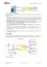
2.8
External SEGGER J-
Link™
debug interface
External target hardware can be connected to J3 for firmware programming and debug. The
SEGGER debug interface is implemented as shown in Figure 11. J3 is implemented with a 2x5
10-pin header on 1.27 mm centers.