


Service Bulletin
20
UAV-1005757-001 Rev A
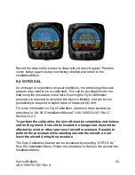
5. Rotate the knob until you see
“SW PART NUM”. Confirm part number
matches that shown in Table 5-1 Software Update Files.
6. Rotate the
knob until you see “SW VERSION”. Confirm version matches
that shown in Table 5-1 Software Update Files.
7. Rotate the
knob until you see “SW CHECKSUM”. Confirm checksum
matches that shown in Table 5-1 Software Update Files. Note that the
checksum is not case sensitive.
If all software fields match, continue with these instructions. Otherwise,
contact uAvionix Support.
The following sections detail new Installation Menu options and should be
reviewed and set appropriately for your aircraft. Access the Installation
Menu and rotate the center knob to select these settings.
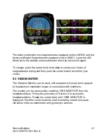
9.1 SERIAL 3
Follow the procedure in Section 9 to access the Installation Menu. Rotate
the center knob until “SERIAL 3” is displayed. SERIAL 3 will be set to
“AVLINK” after update. This will enable the AV-Link MFD screen. If not AV-
Link is installed, this setting should be set to NONE.
9.2 AID MODE
There are 3 options for the AID MODE. With the internal magnetometer
installed (P/N UAV-1004035-002), you can now choose from 3 options:
•
None = Magnetometer will not be referenced.
•
MAG1 = Magnetometer provides correction data to DG
•
MAG2 = Magnetometer provides correction data to DG and aiding to
core AHRS algorithm
Follow the procedure in Section 9 to access the Installation Menu. Rotate
the center knob until “AID MODE” is displayed. If the hardware addition of
the internal magnetometer is found then you will have a choice of NONE,
MAG 1, and MAG 2. If the internal magnetometer is not found, only
“NONE” will be displayed.