


SARA-G3 series - System Integration Manual
UBX-13000995 - R06
Objective Specification
Design-in
Page 97 of 218
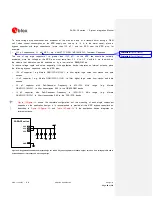
Reference
Description
Part Number - Manufacturer
C1, C2
10 µF Capacitor Ceramic X5R 0603 20% 6.3 V GRM188R60J106ME47 - Murata
R1
47 k
Ω
Resistor 0402 5% 0.1 W
RC0402JR-0747KL - Yageo Phycomp
R2
9.1 k
Ω
Resistor 0402 5% 0.1 W
RC0402JR-079K1L - Yageo Phycomp
R3
3.9 k
Ω
Resistor 0402 5% 0.1 W
RC0402JR-073K9L - Yageo Phycomp
U1
LDO Linear Regulator ADJ 3.0 A
LT1764AEQ#PBF - Linear Technology
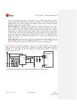
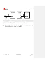
Table 15: Suggested components for VCC voltage supply application circuit using an LDO linear regulator
2.1.1.4
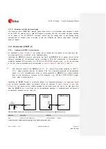
Guidelines for VCC supply circuit design using a rechargeable Li-Ion or Li-Pol battery
Rechargeable Li-Ion or Li-Pol batteries connected to the
VCC
pins should meet the following prerequisites
to comply with the module
VCC
Maximum pulse and DC discharge current
: the rechargeable Li-Ion battery with its output circuit must be
capable of delivering 1.9 A current pulses with 1/8 duty-cycle to the
VCC
pins and must be capable
of delivering a DC current greater than the module maximum average current consumption to
VCC
pins. The maximum pulse discharge current and the maximum DC discharge current are not always
reported in battery data sheets, but the maximum DC discharge current is typically almost equal to the
battery capacity in Amp-hours divided by 1 hour
DC series resistance
: the rechargeable Li-Ion battery with its output circuit must be capable of avoiding
a VCC voltage drop greater than 400 mV during transmit bursts
2.1.1.5
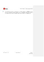
Guidelines for VCC supply circuit design using a primary (disposable) battery
The characteristics of a primary (non-rechargeable) battery connected to
VCC
pins should meet the
following prerequisites to comply with the module
VCC
Maximum pulse and DC discharge current
: the non-rechargeable battery with its output circuit must be
capable of delivering 1.9 A current pulses with 1/8 duty-cycle to the
VCC
pins and must be capable
of delivering a DC current greater than the module maximum average current consumption at the
VCC
pins. The maximum pulse and the maximum DC discharge current is not always reported in battery
data sheets, but the maximum DC discharge current is typically almost equal to the battery capacity in
Amp-hours divided by 1 hour
DC series resistance
: the non-rechargeable battery with its output circuit must be capable of avoiding
a VCC voltage drop greater than 400 mV during transmit bursts
2.1.1.6
Additional guidelines for VCC supply circuit design
To reduce voltage drops, use a low impedance power source. The resistance of the power supply lines
(connected to the
VCC
and
GND
pins of the module) on the application board and battery pack should
also be considered and minimized: cabling and routing must be as short as possible to minimize power
losses.
Three pins are allocated for
VCC
supply. Another twenty pins are designated for
GND
connection. Even if
all the
VCC
pins and all the
GND
pins are internally connected within the module, it is recommended to
properly connect all of them to supply the module to minimize series resistance losses.


