background image


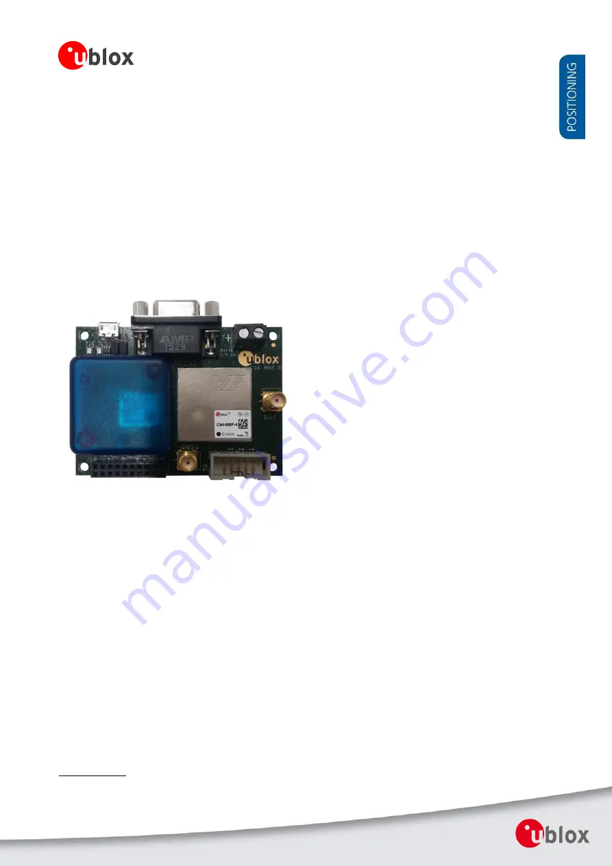
C94-M8P 

u-blox RTK Application Board Package 

User Guide


Abstract


This document describes the structure and use of the C94-M8P RTK 
application board package  and provides information for evaluating 
and  testing  the  u-blox  NEO-M8P  high  precision  positioning 
modules.


www.u-blox.com


UBX-15031066 - R06 

Summary of Contents for C94-M8P

Page 1: ...ser Guide Abstract This document describes the structure and use of the C94 M8P RTK application board package and provides information for evaluating and testing the u blox NEO M8P high precision positioning modules www u blox com UBX 15031066 R06 ...

Page 2: ...re FLASH version PCN reference C94 M8P C94 M8P 1 10 FLASH FW3 01 HPG1 30 N A C94 M8P C94 M8P 2 10 FLASH FW3 01 HPG1 30 N A C94 M8P C94 M8P 3 10 FLASH FW3 01 HPG1 30 N A C94 M8P C94 M8P 4 10 FLASH FW3 01 HPG1 30 N A u blox reserves all rights to this document and the information contained herein Products names logos and designs described herein may in whole or in part be subject to intellectual pro...

Page 3: ...mance Warnings and certifications CAUTION IN THE UNLIKELY EVENT OF A FAILURE IN THE INTERNAL PROTECTION CIRCUITRY THERE IS A RISK OF AN EXPLOSION WHEN CHARGING FULLY OR PARTIALLY DISCHARGED BATTERIES REPLACE THE BATTERY IF IT NO LONGER HAS SUFFICIENT CHARGE FOR UNIT OPERATION CONTROL THE BATTERY BEFORE USING IF THE DEVICE HAS NOT BEEN OPERATED FOR AN EXTENDED PERIOD OF TIME Products marked with th...

Page 4: ...8 3 2 1 GNSS antenna considerations 8 3 3 Updating firmware on C94 M8P 9 3 4 Configuration 9 3 4 1 GNSS module configuration 9 3 4 2 Base Station configuration 10 3 4 3 Rover configuration 13 4 Operation 14 4 1 Base in operation 14 4 2 Rover in operation 14 4 2 1 Monitoring the quality of the RTCM stream 15 5 Evaluation interfaces 16 5 1 RS232 UART Interface 16 5 2 USB interface 16 5 3 J8 connecto...

Page 5: ...Appendix 22 A Glossary 22 B Radio communication link configuration 22 B 1 Serial console terminal installation 25 C Notes on FW3 01 HPG1 30 26 D Notes on hardware 26 D 1 Variants 00 26 D 1 1 Overview 26 D 1 2 Connectors 26 D 1 3 Dimensions 27 Related documents 28 Revision history 28 Contact 29 ...

Page 6: ...anada 915 MHz C94 M8P 3 10 or C94 M8P 3 10 for Europe 433 MHz C94 M8P 4 10 for Japan 920 Mhz A label showing the application variant ordering code is located at the top right corner of the board For information about variants with the old board version C94 M8P 1 00 C94 M8P 2 00 and C94 M8P 3 00 refer to Appendix D 1 1 2 C94 M8P package includes The C94 M8P package includes 2 application boards bot...

Page 7: ...232 for radio link configuration Connection pins for UART communication e g C027 3 3 V SMA connector External GNSS antenna and UHF antenna Dimensions 75 mm x 55 mm Weight 35 g Power Supply 5 V via USB or externally powered by battery 5 05 mm pitch 2 pin 3 7 V 20 V powered 1 battery connector Normal Operating temperature 40 C to 65 C Table 1 C94 M8P application board specification ...

Page 8: ...differently The two boards are identical Select one of the boards to act as a Base and one as a Rover 3 2 1 GNSS antenna considerations In order to optimize the benefit of u blox s Real Time Kinematic RTK technology and achieve high accuracy performance the placements of the antennas are extremely important The recommendations for the GNSS antenna used with the system are The antenna needs to be p...

Page 9: ... and track multiple GNSS systems The NEO M8P module is configured by default for concurrent GPS and GLONASS reception where both constellations will be used in an RTK solution Other available configurations are GPS only and GPS BeiDou reception A GPS only setup can be used if higher RTK update rate is of interest The default GNSS constellation is GPS GLONASS For most users this is the optimal conf...

Page 10: ...e must be the same as the Navigation Rate of Base station which is 1 Hz by default RTCM messages do not need to be configured differently even if the Navigation Rate of the Rover is configured differently e g to have a higher output rate than the default 1 Hz Individual RTCM messages should be configured at the same rate The throughput of the RTCM communications link must be considered with respec...

Page 11: ...e to output the RTCM reference station position message needed by the Rover The current firmware requires five ambiguities to attempt fixing The RTK fixed status can therefore be reached when either of the following requirements is fulfilled 1 six satellites from a single constellation are available or 2 eight satellites from two different constellations are available Disable NMEA disable child me...

Page 12: ...ion time regardless of the actual number of valid fixes that were used for position calculation Reasonable values range from one day for applications that require high absolute accuracy to a few minutes for applications that only require high relative accuracy The second field Required Position Accuracy forces the calculated Base station position to be of at least the given 3D position accuracy Na...

Page 13: ...r will automatically apply the RTCM corrections it receives In effect it will immediately enter RTK float mode and assuming circumstances allow for it eventually reach RTK fixed mode In order to mitigate position jumps when switching between fixed and float modes you can use RTK float only mode Select it using the u center message UBX CFG DGNSS In this mode the Rover will estimate the ambiguities ...

Page 14: ...2 Rover in operation When the Rover device is in normal operation the Data View in u center shows FLOAT or FIXED to indicate the current operation mode Figure 9 Data View shows FLOAT or FIXED on Rover Additionally the message UBX NAV RELPOSNED in u center shows more details about relative positions and accuracies For more information refer to the u center User Guide 4 the u blox 8 u blox M8 Receiv...

Page 15: ...continued carrier phase tracking is important 4 2 1 Monitoring the quality of the RTCM stream You can monitor the quality of the RTCM stream that the Rover receives Use UBX RXM RTCM message to see station ID message type and CRC status Low latency 5 s of the RTCM3 stream is critical for achieving a RTK FLOAT FIXED solution at the Rover Any communication issues will prevent RTK FLOAT FIXED being ac...

Page 16: ...CM messages sent from the radio module to the GNSS module Before configuring the radio module the UART output of the GNSS module needs to be disabled See section Appendix B for radio communication link configuration 5 2 USB interface The C94 M8P board provides one micro A USB interface which is used for Configuring the GNSS NEO M8P 2 module Logging data sent out from the GNSS module including UBX ...

Page 17: ...d to an external battery or DC supply This uses a standard 5 05 mm pitch 2 pin connector for supplying a 3 7 20 VDC source or external battery The pin assignments of this 2 pin connector are shown in Error Reference source not found Pin Nr Assignment 1 V_BAT battery 2 GND battery Table 3 Pin assignments of battery connector 5 5 LED The Blue LED DS2 mounted on the C94 M8P application board shows th...

Page 18: ...Advance Information Evaluation interfaces Page 18 of 29 5 6 2 GNSS antenna connector The GNSS module SMA connector on each board is used to connect the external active GNSS antenna This connector is marked with the text GNSS on the board ...

Page 19: ...C94 M8P User Guide UBX 15031066 R06 Advance Information Block diagram Page 19 of 29 6 Block diagram Figure 12 Block diagram of the C94 M8P application board ...

Page 20: ...C94 M8P User Guide UBX 15031066 R06 Advance Information Board layout Page 20 of 29 7 Board layout Figure 13 Board Layout of C94 M8P Application Board ...

Page 21: ...C94 M8P User Guide UBX 15031066 R06 Advance Information Schematic Page 21 of 29 8 Schematic Figure 14 Schematics of C94 M8P application board ...

Page 22: ... TTFF Time To First Fix UART Universal Asynchronous Receiver Transmitter Table 5 Explanation of abbreviations used B Radio communication link configuration By default users do not need to do any configuration for the Radio communication link The u blox default configurations are tested and verified Users need to take all responsibility for any changes against the default configuration By default u...

Page 23: ...rs need to take all responsibility for any changes to the default configuration The C94 M8P application board uses a HM TRP radio module with SiK open source firmware which supports a subset variant of the Hayes AT modem commands for advance configuration Before configuring the radio module the GNSS module UART output needs to be disabled via u center View Message View UBX CFG PRT as shown in Figu...

Page 24: ...respondingly In case of wrong AT commands the radio module returns ERROR as the response Figure 18 Send AT commands to Radio Module Table 5 shows the AT command set that is supported by the C94 M8P application board Table 6 shows all radio parameters that are configurable For more information about configuring the radio module used by C94 M8P see http copter ardupilot com wiki common 3dr radio adv...

Page 25: ...Network ID Must be same for the pair of C94 M8P boards Must be same for a pair of radios 4 TXPOWER Transmit power in dBm maximum value is 20 dBm 5 ECC Enables disables the golay error correcting code Must be same for a pair of radios 6 MAVLINK Configure MAVLink framing and reporting 0 no mavlink default 1 frame mavlink 2 low latency mavlink 8 MIN_FREQ Minimum frequency in kHz Must be same for a pa...

Page 26: ...z should be contemplated carefully owing to the radio modem latency In any event the modem interface rate of 192009600 baud will present a hard limit depending on the number of satellites e g approximately 4 Hz with 12 satellites D 1 Variants 00 Variants using the old board version C94 M8P 1 00 C94 M8P 2 00 and C94 M8P 3 00 have a different board layout than the C94P M8P X 10 versions This chapter...

Page 27: ...rds It enables communication alternatives using u blox cellular and short range technologies The pin assignments of this 4 pin connector are shown in Error Reference source not found For more details about C027 see https www u blox com product c027 Table 8 Pin assignments of J4 LED There are four indicator LEDs mounted on the C94 M8P application board The Blue LED shows the time pulse output signa...

Page 28: ...UBX 16010559 For regular updates to u blox documentation and to receive product change notifications register on our homepage http www u blox com Revision history Revision Date Name Status Comments R01 19 Feb 2016 yzha Advance Information R02 30 May 2016 jhak Restructuring chapters more details on Base Rover configuration FW3 01 HPG1 11 related information R03 19 Aug 2016 jhak Updated package cont...

Page 29: ...m Regional Office China Beijing Phone 86 10 68 133 545 E mail info_cn u blox com Support support_cn u blox com Regional Office China Chongqing Phone 86 23 6815 1588 E mail info_cn u blox com Support support_cn u blox com Regional Office China Shanghai Phone 86 21 6090 4832 E mail info_cn u blox com Support support_cn u blox com Regional Office China Shenzhen Phone 86 755 8627 1083 E mail info_cn u...

Reviews: