- 13 -
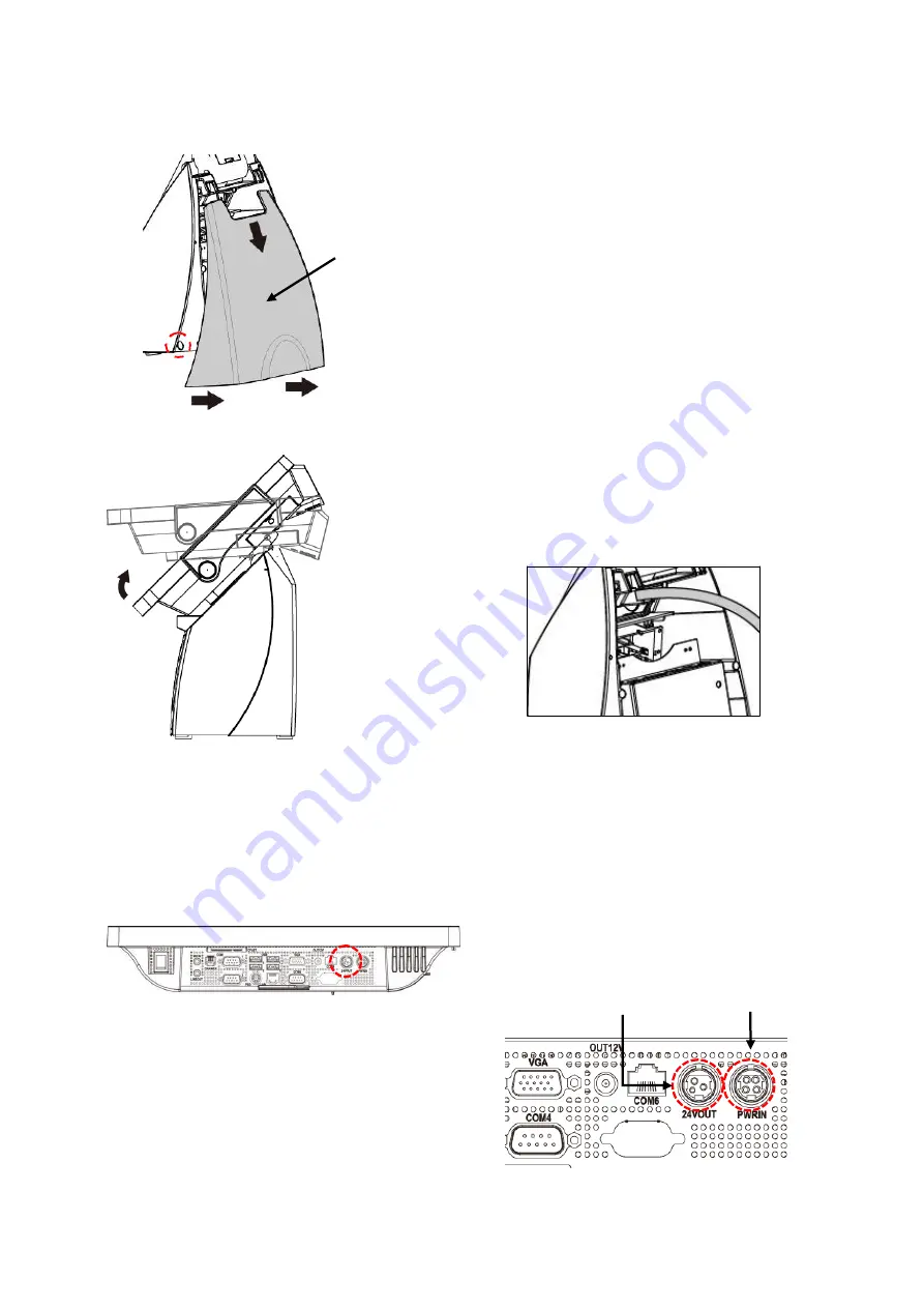
2.3. Plug AC Power Cord to the POS
Magnetic Lock
Rear Cover
Magnetic
Lock
a.
Lift up the rear cover side of the POS.
b.
Slightly pull the two edges of
Magnetic Lock Rear Cover to loosen
the magnetic lock
c.
Pull and remove the Base Rear Cover
(as image left illustrated).
d.
Till the POS unit horizontally.
e.
Pass the connector of power adaptor
through the base.
POS Unit
(Bottom I/O Ports)
f.
Plug the power connector of the AC
power adaptor to the Main Power
Input.
g.
Check the Printer Power Output
connector (pre-connected) is properly
connect to the printer
Printer
Main
Power Output
Power Input
Summary of Contents for POP-650-i
Page 4: ......
Page 8: ......
Page 13: ...5 Dimensions Front View Left View Rear View Right View...
Page 58: ...50 Serial Port 3 to Serial Port 6 Configurations Port 3 Port 4...
Page 60: ...52 3 2 9 Network Stack This section configures settings relevant to the network stack...
Page 65: ...57 3 3 Chipset This field is used to configure the functions of relevant chipset...
Page 70: ...62 3 3 2 System Agent SA Configuration...
Page 73: ...65 Memory Configuration This field displays the memory configuration...
Page 79: ...71...
Page 83: ...75 b Setup is now installing the driver c Setup completed Click Exit to close the program...
Page 90: ...82 c Click Finish to finish the installation...
Page 130: ...122 7 5 5 Jumper Location and Settings...
Page 131: ...123 7 5 6 Jumper Settings...
Page 132: ...124...
Page 133: ...125 20161225...


