background image

-31- 


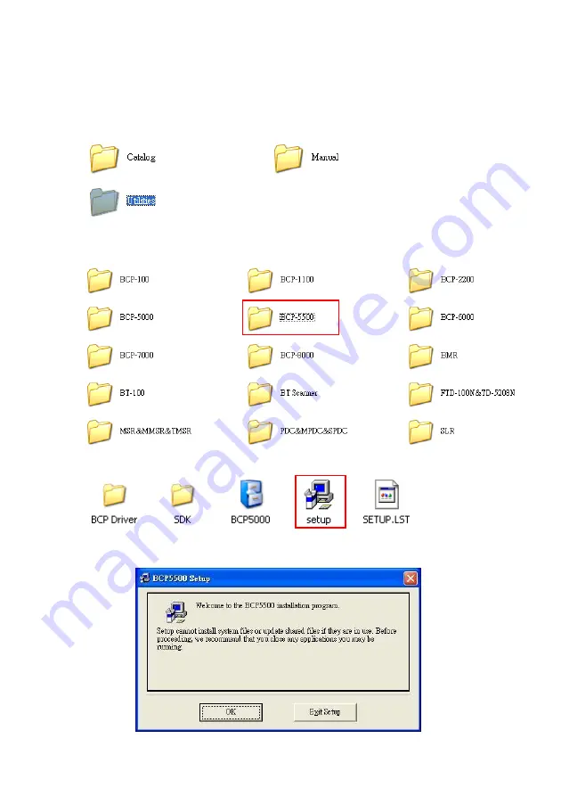
5.2.2  Utility installation 


1. 

Please download the latest driver from TYSSO official website. Browse 
the folder and select folder 

“Utility”. 


2. 

Move the cursor to the folder “BCP-5500” and double click to access 
the sub folders. 


3. 

Double click the “Setup” to start installation. 


4. 

Click “OK” to proceed. 

Summary of Contents for BCP-5500 Series

Page 1: ...BCP 5500 Barcode Data Collector Ver 1 1 Copyright Fametech Inc TYSSO 2013 User Manual...

Page 2: ......

Page 3: ...y via USB Interface of Computer 9 3 1 2 Charge the battery via RS 232 Cable and USB Power Cable 9 3 1 3 Charge the battery via RS 232 Cable and Optional Power Adaptor 10 3 2 Battery Care 11 3 2 1 Batt...

Page 4: ...ty installation 31 6 Configuring Your Data Collector Data Management 6 1 Access to the Utility 34 6 2 File 35 6 3 Setting 36 6 3 1 Barcode 37 6 3 2 General Parameter 38 6 3 3 Job Mode Selection 39 6 4...

Page 5: ...will void the warranty may cause malfunction and and may put the User or other person at risk of injury 10 DO NOT aim the product at eyes of people or animals Some product models use a strong light s...

Page 6: ...ges of high speed scanning reliability and easy operation In addition it also gives the operators greater mobility for scanning those tough to reach barcodes The embedded utility software provides use...

Page 7: ...28x64 dot matrix graphic LCD with back light 18 character x 4 line 7x18 dot display pattern Keypad 3 keys 2 navigation keys and enter key Indicator LED Indicator Audio Notification Audio Buzzer Vibrat...

Page 8: ...r 136 1 g cradle 170 2 g Dimension 175 x 45 x28 mm Operating Temperature 0 C 45 C Operating Humidity 10 85 RH non condensing Storage Temperature 20 C 65 C Storage Humidity 5 95 RH non condensing The s...

Page 9: ...Display 4 Navigation Buttons Arrow Up Enter Arrow Down 5 Scan Trigger 6 Connector to Recharge and Communication Cradle 7 Wrist Strap Hole 8 LED Indicator Recharge and Communication Cradle 9 Connector...

Page 10: ...8 Recharge and Communication Cradle...

Page 11: ...puter 1 Turn on the computer 2 Connect the USB connector to the USB port on the computer 3 Install the data collector to the recharge and communication cradle The data collector is activated and the b...

Page 12: ...tery is recharging automatically There is a beep sound and the LED indicator lit RED steadily 5 As the battery is fully charged the LED indicator lit GREEN to indicate the battery charge is completed...

Page 13: ...llector is activated and the battery is recharging automatically There is a beep sound and the LED indicator lit RED steadily 6 As the battery is fully charged the LED indicator lit GREEN to indicate...

Page 14: ...ttery nears the end of its usable life it is necessary to replace a new battery Before replacing the battery turn off the data collector press and hold the scan trigger for over 5 seconds until the di...

Page 15: ...ector press and hold the scan trigger for about 5 seconds the LED indicator of the data collector will blink RED twice and then switch off LED Blink x2 OFF When the data collector is connected to the...

Page 16: ...a Collector Point the data collector with the RED Light alignment projected horizontally to the barcode Adjust the distance to capture the barcode and the beep sound will notice you that the data is c...

Page 17: ...n In Mode 0 data collector performs scan process and save the scanned data immediately as the scan trigger is pressed The scanned data is displayed on the LCD and ready for scan User can perform fast...

Page 18: ...imeto delete thedata To quit without deleting the data Press Enter Key to exit 12 02 10 17 16 07 BCP 4200 USB Delete No Yes 5 The display data shows the data status The row Data Deleted indicates that...

Page 19: ...ger the display will show the scanned barcode data and ask user to enter the quantity as image below illustrated 12 02 10 17 16 07 BCP 4200 USB Q ty 0 Shift Count To enter the quantity Use the Navigat...

Page 20: ...add adigit 12 02 10 17 16 07 BCP 4200 USB Q ty 40 Shift Count 3 Press the Arrow Down Key Count eight times toenterthe Second Digit 8 12 02 10 17 16 07 BCP 4200 USB Q ty 48 Shift Count 4 Press the Arr...

Page 21: ...o confirm the data 12 02 10 17 16 07 BCP 4200 USB Q ty 485 Navigation and Data Management 12 02 10 17 16 07 BCP 4200 USB Q ty 485 User can examine the scanned data by using the Navigation Keys andpres...

Page 22: ...nter Key to confirm 3 The display will show the detailed information of the selected data 4 To delete the selected data Press the two Navigation Keys atthesametimeto delete thedata 12 02 10 17 16 07 B...

Page 23: ...g the Navigation Keys there is a mark Data Erased to indicate the deleted scan data 12 02 10 17 16 07 Data Erased Q ty 485 Note To delete all the scanned data in the data collector please use configur...

Page 24: ...r of the receiver Recharge Communication Cradle lit RED to indicate that the receiver cradle is functioning 4 Install the data collector to the cradle The data collector is activated automatically and...

Page 25: ...radle The data collector is activated automatically and a beep sound indicates that the data collector is properly installed 7 When first connect to the computer install the driver and Utility Now use...

Page 26: ...ditional COM port available to the PC and application software can access the USB device in the same way as it would access a standard COM port Note Please refer to your technical support of the appli...

Page 27: ...25 4 Double click the file to start the installation 5 Install Wizard is initiated and prepares to install...

Page 28: ...26 Click Next to continue 6 License Agreement Accept the agreement and click Next to proceed...

Page 29: ...27 7 Choose destination Click Next to continue 8 Click Install to start installation...

Page 30: ...28 9 Install Wizard is finished Click Finish to proceed 10 Here we need to install the USB to UART Bridgedriver Click Install to continue...

Page 31: ...29 11 The system is scanning the port configuration 12 The USB to UART driver is successfully installed Click OK to exit...

Page 32: ...30 13 COM Port User can examine the Device Manager of the system and find the section Ports COM LPT to find the USB to UART Bridge virtual COM port for USB interface...

Page 33: ...ad the latest driver from TYSSO official website Browse the folder and select folder Utility 2 Move the cursor to the folder BCP 5500 and double click to access the sub folders 3 Double click the Setu...

Page 34: ...the button to start installation Note To change the directory click Change Directory to assign the directory desired 6 Setup will add group name BCP5000 to the group box automatically Click Continue...

Page 35: ...33 7 Wait for several seconds while the installation is processing 8 Installation completed Click Ok to exit...

Page 36: ...barcode data via the configuration utility 6 1 Access to the Utility Comm Port Select the proper COM port to establish the communication between the computer and the data collector Note Select the cor...

Page 37: ...o perform Transmit to transmit default settings to the data collector Open this function allows user to reload the configuration parameter file previously saved in order to restore the specified setti...

Page 38: ...settings of the data collector Barcode the settings of the supported barcodes General Parameter user can select the conversion of the scanned data in upper lower case and the buzzer settings Job Mode...

Page 39: ...configure the parameters of the barcode 1 Select and click the icon to access the menu 2 Select the barcode type desired and configure the barcode settings enable disable check character etc 3 Click A...

Page 40: ...arcode This function can prevent user from pressing the trigger accidently and scan the same barcode twice The data collector may not save the data as if the same barcode is scanned twice within 3 sec...

Page 41: ...to Job Mode page 14 for detail instructions To select the Job Mode desired 1 Click the mode required The menu will display the data format of the job mode Mode 0 Mode 1 2 Click Accept to complete the...

Page 42: ...40 Customized Mode Data Format There are more customized data formats available as the image below illustrated Please refer to the local representative for further information...

Page 43: ...e menu 2 Make sure the scanned data is uploaded or new settings are configured before perform transmission Warning All the data stored in the data collector will be erased when performing the transmis...

Page 44: ...42 3 Click Transmit button 4 There are descending beeps and a pop up window displays on the monitor to indicate that the transmission is completed Click OK to exit...

Page 45: ...43 6 5 Upload the Data to the Computer The function allows user to upload examine the data collected by the data collector Click the icon Upload Data to access the menu...

Page 46: ...ata Format Upload and save the data records in raw data format Upload Data from BCP in Text Format Upload and save the data in text file directly Convert Raw Data to Text File The uploaded raw data ca...

Page 47: ...45 Uploaded Data Raw Format Uploaded Data Text Format...

Page 48: ...ata in BCP This function is to erase the scanned data in the data collector Warning It is impossible to recover the data after the data are erased Make sure to upload and save the records before execu...

Page 49: ...By enabling this function only the authorized user can access the utility to configure the data collectors and perform data management 1 Select Change Password and click OK to continue 2 Enter the cur...

Page 50: ...lector to the computer and add the timestamp to the data 1 Select Enable Disable Real Time Clock and click OK to continue 2 Click enable to initiate the Real Time Clock RTC 3 It s recommended to perfo...

Page 51: ...he pop up window indicates that the Real Time Clock function is enabled and the time tamp is added to the data stored in the data collector 6 The Upload Data Status indicates the Real Time Clock is ac...

Page 52: ...50 User can perform Upload the Data page 44 and the records have timestamp added Uploaded Data without Timestamp Uploaded Data with Timestamp...

Page 53: ...to the computer Each data collector has the fixed machine ID preset in factory When the data collecting task is in process with multiple data collectors it is convenient to identify the uploaded data...

Page 54: ...setting 1 Select Enable Disable Upload Data With Machine ID and click OK to continue 2 There is a pop up window displays on the monitor Select Enable and click OK to confirm 3 The Upload Data Status i...

Page 55: ...53 User can perform Upload the Data page 44 Upload the Data The machine ID is added to the uploaded data Uploaded Data with Machine ID...

Page 56: ...54 7 Appendix Scan Zone BCP 5500 N BCP 5500 C...

Page 57: ...n Blink GREEN 1 beep sound scan trigger pressed Connecting to Computer via Recharge Communication Cradle Status Operation Data collector LED Indicator Audio Connecting to computer Battery Charge Lit R...

Page 58: ...mory Full Status Operation Data collector LED Indicator Audio Memory Near Full scan trigger pressed Blink RED Blink GREEN 1 beep sound Memory Full scan trigger pressed Lit RED steadily Continuous beep...

Page 59: ...57...

Page 60: ...Feb 2013...

Reviews: