background image

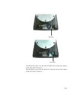
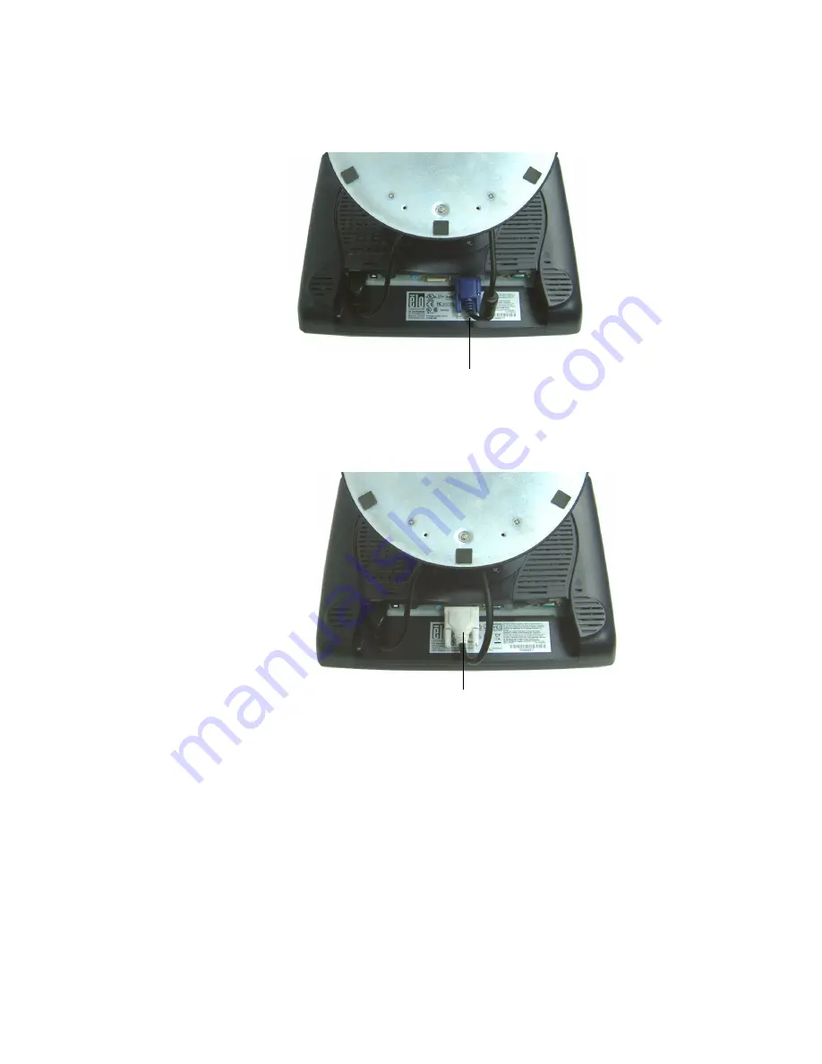
Video cable

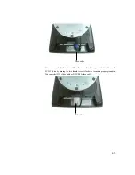
Connect one end of the video cable to the rear side of computer and the other to the

LCD. Tighten by turning the two thumb screws clockwise to ensure proper grounding.

You can select DVI video cable or D-SUB15 video cable.

DVI cable

2-19

Summary of Contents for 1529L

Page 1: ...Touchmonitor User Guide 1529L 15 LCD Desktop Touchmonitor 3000 series Optional Magnetic Stripe Reader Barcode Scanner Customer Display and Biometric available Shown with optional peripherals ...

Page 2: ...Elo TouchSystems 15 LCD Touchmonitor Optional Magnetic Stripe Reader Customer Display Barcode Scanner User Guide Revision G P N 008603E Elo TouchSystems 1 800 ELOTOUCH www elotouch com ...

Page 3: ...reof and specifically disclaims any implied warranties of merchantability or fitness for a particular purpose Tyco Electronics reserves the right to revise this publication and to make changes from time to time in the content hereof without obligation of Tyco Electronics to notify any person of such revisions or changes TrademarkAcknowledgments AccuTouch CarrollTouch Elo TouchSystems IntelliTouch ...

Page 4: ...apter 3 Operation 30 AboutTouchmonitorAdjustments 30 15 LCD Function Key 31 Controls andAdjustment 32 OSDLock Unlock 32 Power Lock Unlock 32 OSDMenuFunctions 32 OSDControlOptions 33 Brightness 33 Contrast 33 Sharpness 33 Phase 33 Auto Adjust 33 OSDLeft Right 33 OSDUp Down 33 Clock 33 ColorTemperature 33 CurrentInput 33 OSDPosition 33 Language 33 RecallDefaults 33 OSDTimeout 33 Input Video Select 3...

Page 5: ...tions They are AccuTouch Intellitouch and carrollTouch and Acoustic Pulse Recognition The fingerprint reader translates illuminated images of fingerprints into digital code for further software processing e g enrollment fingerprint registration and verification authentication of registered users The fingerprint reader uses the SEIR method and CMOS image sensor to capture high contrast high resolut...

Page 6: ...Both scanners run on a USB interface Detailed LCD Display Performance Requirements 15 inch TFT LCDDisplay Panel Display Format 1024 x 768 Display area 15 304 1mm H x 228mm V Pixel Pitch 15 0 297mm H x 0 297mm V Contrast Ratio 500 1 typical Brightness LCD 350 cd m2 Typical 270 cd m2 Minimum AccuTouch 280 cd m2 Typical 203 cd m2 Minimum IntelliTouch 315 cd m2 Typical 230 cd m2 Minimum CarrollTouch 3...

Page 7: ... per row 20 Number of rows 2 Character 5x7 dot matrix configuration Character Height 9 5mm Character width 6 2mm Character ASCII configuration Character color Blue green MTBF 300 000 hours Fingerprint Reader There is a fingerprint reader in the USB version only General Description FDU01B is a PC peripheral FRD Fingerprint Recognition Device for USB Universal Serial Bus connections 1 3 ...

Page 8: ...e Capture Error Rate 0 1 Life Time Typically 40 000Hrs Credit Card Reader There is a USB credit card reader only The USB version is available in HID and Key board emulation versions The reader reads all three stripes on a standard credit card or drivers license Reference Standards Conform to International Standards Organization American National Standards applicable standards Institute California ...

Page 9: ...r display The hub also supplies two USB ports to the outside of the back of the 1529L for external use The hub is only used by the USB version of the 1529L The hub meets the following requirements Specification Full compliance with USB specification 1 0 1 1 and HID Class Definition Rev 1 0 Hub shall be self powered Hub shall provide 2 external and 4 internal downstream ports with individual port o...

Page 10: ... LCD touchmonitor and how to install Elo TouchSystems driver software Unpacking Your Touchmonitor Check that the following items are present and in good condition Touchmonitor USB Cable Video cable Power cable US Candian European power cable DVI cable Speaker CD and Quick Install Guide ...

Page 11: ...Product Overview Main Unit Note Shown with optional Biometric MSR Rear View Note Shown with optional Rear Facing Customer Display 2 7 ...

Page 12: ...2 8 Side View Base Bottom View or ...

Page 13: ...Kensington TM Lock The KensingtonTM lock is a security device that prevents theft To find out more about this security device do to http www kensington com 2 9 ...

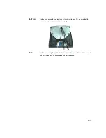
Page 14: ...USB cable For Windows 2000 Me and XP systems only To set up the display please refer to the following figures and procedures Remove the Cable Cover The cables are connected at the back of the monitor cable cover To remove the cover grasp the lip of the cover and pull towards you until it snaps off ...

Page 15: ...ables to your touchmonitor and PC be sure that the computer and touchmonitor are turned off NOTE Before connecting the cables to the touchmonitor route all the cables through the hole in the second as shown in the picture above 2 11 ...

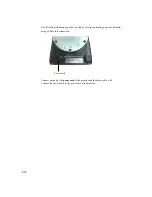
Page 16: ...ons guide you step by step in connecting your touchmonitor using a USB cable connection Power cord Connect one end of the power cord to the monitor and the other end to wall Connect the power cable to the power port in the monitor ...

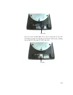
Page 17: ...e end of the video cable to the rear side of computer and the other to the LCD Tighten by turning the two thumb screws clockwise to ensure proper grounding You can select DVI video cable or D SUB15 video cable DVI cable 2 13 ...

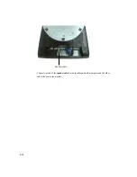
Page 18: ...2 14 Speaker cable Connect one end of the speaker cable to the speaker port in the computer and the other end to the port in the monitor ...

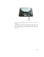
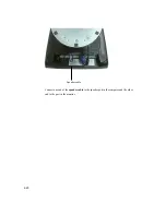
Page 19: ... other to the LCD monitor The USB cable is for optional touch MSR CD and Finger Print Reader Only one USB cable is needed because the device contains a self powered USB 1 1 Hub Two self powered ports are available for running other USB devices For touch only no USB Hub is present 2 15 ...

Page 20: ...les USB cable For Windows 2000 Me and XP systems only To set up the display please refer to the following figures and procedures Remove the Cable Cover The cables are connected at the back of the monitor cable cover To remove the cover grasp the lip of the cover and pull towards you until it snaps off ...

Page 21: ...ables to your touchmonitor and PC be sure that the computer and touchmonitor are turned off NOTE Before connecting the cables to the touchmonitor route all the cables through the hole in the second as shown in the picture above 2 17 ...

Page 22: ...ons guide you step by step in connecting your touchmonitor using a USB cable connection Power cord Connect one end of the power cord to the monitor and the other end to wall Connect the power cable to the power port in the monitor ...

Page 23: ...e end of the video cable to the rear side of computer and the other to the LCD Tighten by turning the two thumb screws clockwise to ensure proper grounding You can select DVI video cable or D SUB15 video cable DVI cable 2 19 ...

Page 24: ...2 20 Speaker cable Connect one end of the speaker cable to the speaker port in the computer and the other end to the port in the monitor ...

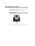
Page 25: ...terface connect one end of the USB cable to the rear side of the computer and the other to the LCD monitor For Serial interface connect one end of the RS 232 cable to the rear side of the conputer and the other to the LCD monitor 2 21 ...

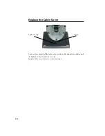
Page 26: ...Cable Cover Cable cover lip cables Then you have attached all the cables to the monitor gently bring all the cables toward the standard so they fit under the cover lip Snap the Cable cover in place over the connections ...

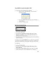
Page 27: ...529L Driver Install Drivers 2 Double click setup exe Follow the Install Shield Wizard procedure to complete the installation For a detailed software development kit browse to Touch Monitor Peripherals Finger Print Readers Fingerprint Reader 229L 1529L Driver Install Drivers and open the following files FDxSDKforWindows1 20 zip SecuBSPSDK for Windows2 10 zip You will enter one of the following seri...

Page 28: ...d Readers Demo 2 Open the Readme txt and follow instructions to test the unit Convert MSR from HID to keyboard Emulation 1 To convert from HID mode to Keyboard Emulation mode 1 1 Double click on the MSR Change Mode icon on the desktop The following will appear 1 2 The dim box will indicate the current setting Click the Keyboard Mode to switch to Keyboard Emulation mode 1 3 Click Quit to close the ...

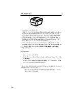
Page 29: ...rs Click on the folder that has the name of your operating system for the necessary drivers 3 Once in this folder open up the zip file and open the install text file for further driver installation instructions Note If your software requires OPOSDrivers it is available in the following location Touch Monitor Peripherals Rear Facing Customer Display Drivers OPOS Drivers Test Applications 1 Insert y...

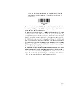
Page 30: ...operating system should guide you through the rest of the installation process If any files are requested please provide the following pathname in your Elo TouchTools CD Touch Monitor Peripherals Barcode Scanner Startup Drivers Test Applications 1 Insert your Elo TouchTools CD 2 On the CD browse to Touch Monitor Peripherals Barcode Scanner Startup Test Applications 3 Double click on Scanner Test A...

Page 31: ...ically 45 G magnetic field the HE Switch output goes high turns OFF The Hall Effect Switch goes to the USB Controller s DSR input As the HE Switch opens or closes it causes the USB Controller to initiate a USB Interrupt message to the host When the Host Application software detects the DSR input active LOW via the USB Interrupt and a CDC message HE Switch is ON it sends a Continuous Trigger SSI co...

Page 32: ...tems are available on the Elo TouchSystems web site at www elotouch com The Elo touchmonitor is plug and play compliant Information on the video capabilities of your touchmonitor is sent to your video display adapter when Windows starts If Windows detects your touchmonitor follow the instructions on the screen to install a generic plug and play monitor Refer to the following appropriate section fo...

Page 33: ... com port on the PC 1 Insert the Elo CD ROM in your computer s CD ROM drive 2 If the AutoStart feature for your CD ROM drive is active the system automatically detects the CD and starts the setup program 3 Follow the directions on the screen to complete the driver setup for your version of Windows 4 If the AutoStart feature is not active 5 Click Start Run 6 Click the Browse button to locate the El...

Page 34: ...solution that is 1280 x 1024 at 80k 75 Hz Use theDisplay control panel in Windows to choose 1280 x 1024 resolution Operating in other resolutions will degrade video performance For further information Please refer to Appendix A All adjustments made to the controls are automatically memorized This features saves you from having to reset the choices every time the touchmonitor is unplugged or powere...

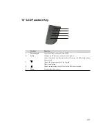
Page 35: ...ect Displays the OSD menus on the screen and used to select Clockwise and Counter clockwise direction the OSD control options on the screen 3 Adjusts the decreasing value of the selected OSD control option 4 Adjusts the increasing value of the selected OSD control option 5 Menu Menu display and menu exit 3 31 ...

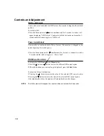
Page 36: ...ess the Menu button and the simultaneously for 2 seconds A window for another 2 seconds and the window toggles to Power Lock OSD Menu Functions To display the OSD Menu press the Menu button 1 Press the button or button to select the different OSD control option 2 When the function you want to change is displayed press the Select button To adjust the Value of the function 1 Pressing the button incr...

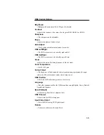
Page 37: ...Clock Adjusts the ratio of dividing frequency of the dot clock Color Temperature Sets R G B gain Current Input The frequency of the horizontal vertical synchronizing signal under the input indicated This information is under Auto Adjust icon OSD Position Allows the OSD indication position to be selected Language Select the language used for the OSD menu from among English France Deutsch Spanish an...

Page 38: ...witch on this LED lights in green The LED indicates the different power status with altered LED colors when monitor operates in different modes see following table Power Mode Consumption Indicator On 50w max Green Sleep 4w max Orange Off 2w NO We recommend switching the monitor off when it is not in use for a long period of time Display Angle For viewing clarity you can tilt the LCD forward up 67 ...

Page 39: ...CAUTION In order to protect the LCD be sure to hold the base when adjusting the LCD and take care not to touch the screen 3 35 ...

Page 40: ...ess the Menu button and the simultaneously for 2 seconds A window for another 2 seconds and the window toggles to Power Lock OSD Menu Functions To display the OSD Menu press the Menu button 1 Press the button or button to select the different OSD control option 2 When the function you want to change is displayed press the Select button To adjust the Value of the function 1 Pressing the button incr...

Page 41: ...screen is moved horizontally left and right OSD Up Down The OSD screen is moved vertically up and down Clock The ratio of dividing frequency of the dot clock is adjusted Color Temperature Sets the R G and B gains Current Input The frequency of the horizontal vertical synchronizing signal under the input is indicated These information is under auto Adjust icon OSD Position The osd indication positi...

Page 42: ...efaults Restore all original factory defaults OSD Timeout Adjust how long the OSD menu is displayed Input Video Select Select D SUB Analog dvi Digital signal Volume To increase or decrease the sound level 3 38 ...

Page 43: ...are dim Refer to the About Touchmonitor Adjustments section to adjust the brightness The video is blank 1 During operation the monitor screen may automatically turn off as a result of the Power Saving feature Press any key to see if the screen reappears 2 Refer to the About Touchmonitor Adjustments section to adjust the brightness Screen flashes when initialized Turn the monitor off then turn it o...

Page 44: ...er 3 Operation 1 To reduce the risk of electric shock follow all safety notices and never open the touchmonitor case 2 Turn off the product before cleaning 3 The slots located on the sides and top of the touchmonitor case are for ventilation Do not block or insert anything inside the ventilation slots 4 It is important that your touchmonitor remains dry Do not pour liquid into or onto your touchmo...

Page 45: ...oes get inside have a qualified service technician check it before you power it on again Do not wipe the screen with a cloth or sponge that could scratch the surface To clean the touchscreen use window or glass cleaner Put the cleaner on a clean cloth and wipe the touchscreen Never apply the cleaner directly to the touchscreen Warning This product consists of devices that may contain mercury which...

Page 46: ...B 42 C H A P T E R B TECHNICAL SPECIFICATIONS ...

Page 47: ...r 5 7 msec Tf 2 3 mesc typical AU G150XG01_V1 Display Color 16 2 million color 6 bit FRC Viewing Angle L R 70 o 70 o typical U D 60 o 60 o typical Input Signal VGAAnalog Video R G B Analog 0 7V peak to peak Sync TTL Positive or Negative Composite Sync Sync on green DVI Video Digital TMDS Input Signal Connector 15 Pin D Sub DVI D Front Control Power on off Menu Select OSD Contrast Brightness H V Po...

Page 48: ...15 LCD Touchmonitor 1529L Dimensions 15 LCD Touchmonitor 1529L Dimensions B 44 ...

Page 49: ...onable protection against harmful interference in a residential installation This equipment generates uses and can radiate radio frequency energy and if not installed and used in accordance with the instructions may cause harmful interference to radio communications B Notice to Users in Canada This equipment complies with the Class B limits for radio noise emissions from digital apparatus as estab...

Page 50: ...o cause interference with radio or television reception or any other device a Verify as an emission source by turning the equipment off and on b If you determine that this equipment is causing the interference try to correct the interference by using one or more of the following measures i Move the digital device away from the affected receiver ii Reposition turn the digital device with respect to...

Page 51: ...certifications have been issued for this monitor Argentina S Mark Australia C Tick CanadaCUL Canada IC EuropeCE JapanVCCI Europe Europe Semko United States UL FCC Sweden MPR II LaserNotice CAUTION Laser radiation when open DO NOT STARE INTO BEAM ...

Page 52: ...hall package the allegedly defective Product in its original shipping carton s or a functional equivalent and shall ship to Seller at Buyer s expense and risk Within a reasonable time after receipt of the allegedly defective Product and verification by Seller that the Product fails to meet the warranty set forth above Seller shall correct such failure by at Seller s options either i modifying or r...

Page 53: ...k and agrees to indemnify Seller against and hold Seller harmless from all liability relating to i assessing the suitability for Buyer s intended use of the Products and of any system design or drawing and ii determining the compliance of Buyer s use of the Products with applicable laws regulations codes and standards Buyer retains and accepts full responsibility for all warranty and other claims ...

Page 54: ...tronics Raychem GmbH Tyco Electronics Raychem GmbH Sun Homada Bldg 2F 301 Constitution Drive Elo TouchSystems Division Elo TouchSystems Division 1 19 20 Shin Yokohama Menlo Park CA 94025 Finsinger Feld 1 Diestsesteenweg 692 Kanagawa 222 0033 USA D 85521 Ottobrunn B 3010 Kessel Lo Japan Germany Belgium 800 ELO TOUCH 800 557 1458 Tel 49 0 89 60822 0 Tel 32 0 16 35 2100 Tel 81 45 478 2161 Tel 650 361...

Reviews: