


Setting
IO-Link mode – process data
18
Hans Turck GmbH & Co. KG | T +49 208 4952-0 | F +49 208 4952-264 | [email protected] | www.turck.com
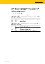
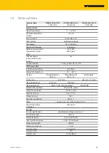
8.3.2
IO-Link mode – process output data
Byte no.
Bit
7
6
5
4
3
2
1
0
0
START
RFU
N_ANT
CMD
1
RFU
NB BLOCK
2
RFU
3
ADDRESS
4…31
DATA 0…27
Meaning of the command bits
Designation
Meaning
START
1
Ò
0 or 0
Ò
1: Execute command. The START bit switches status automatically with the
automatic read
and
automatic write
commands.
0 or 1: Idle
N_ANT
0: Switch on RF field
1: Switch off RF field
CMD
0: No command
1: Automatic read
2: Automatic write
3: Read
4: Write
5: Display UID and time stamp
NB BLOCK
Number of memory blocks to be read or written
n
EEPROM: max. 7 memory blocks
n
FRAM: max. 3 memory blocks
ADDRESS
Address of the first memory block on the tag on which a command is to be executed
DATA 0…27
Write data (LSB…MSB)
The write data is shown in bytes. Observe the block size of the tag used when specifying the
write data:
n
EEPROM: 4 bytes per block
n
FRAM: 8 bytes per block
The device does not output an error message if more than 28 bytes of write data are specified.


