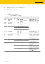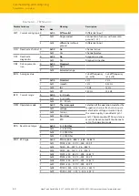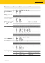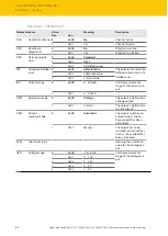
V04.00 | 2021/05
27
6.2.1
QuickConnect and Fast Start-Up applications
Do not use crossover cables in QuickConnect and Fast StartUp applications.
Connect incoming Ethernet cables to P1.
Connect outgoing Ethernet cables to P2.
6.3
Connecting the supply voltage
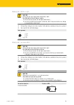
The device is provided with two 4-pin M8 plug connectors for connecting the power supply. V1
and V2 are galvanically isolated.
NOTICE
Interchanging of Ethernet- and power cables
Destruction of module electronic
Observe using the correct M8-connectors when connecting Ethernet and power
cables:
- Ethernet: P1 and P2,
- supply voltage: X1and X2
Fig. 28: M8 Ethernet plug connectors for connecting the fieldbus
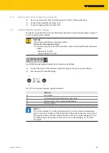
Connect the device to the voltage supply according to the pin assignment below.
Seal unused slots with blind plugs.
1 BN = V1 (+)
2 WH = V2 (+)
3 BU = GND V1
4 BK = GND V2
w
v
X1
X2
2
4
1
3
4
2
3
1
Fig. 29: Pin assignement power supply connectors
Meaning
X1
Power feed
X2
Continuation of the power to the next node
V1
Power supply 1 (incl. supply of electronics)
V2
Power supply 2
NOTE
The system voltage (V1) and the load voltage (V2) are fed in and monitored separ-
ately. In case of an undercut of the admissible voltage, the connectors are switched-
off according to the module's supply concept. In case of an undervoltage at V2, the
LED PWR changes from green to red. In case of an undervoltage at V1, the LED is
turned off.

