Mounting
Grounding the device
24
Hans Turck GmbH & Co. KG | T +49 208 4952-0 | F +49 208 4952-264 | [email protected] | www.turck.com
5.6.3
Grounding the device – I/O and fieldbus level
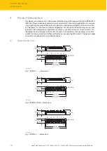
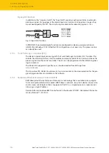
The grounding of the fieldbus level can either be connected directly via the grounding clip (1)
or connected and routed indirectly via an RC element to the grounding of the I/O level. If the
fieldbus grounding is to be routed via an RC element, the grounding clip must be removed.
1
2
3
Fig. 23: Grounding clip (1)
Removing the grounding clip: disconnect the direct grounding of the fieldbus level
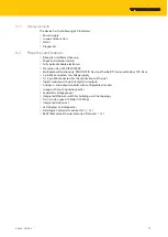
Use a slim slotted screwdriver in order to lift up and remove the grounding clamp.
Fig. 24: Use a flat slotted screwdriver to push the grounding clip forwards and remove it.
Mounting the grounding clip: grounding the fieldbus level directly
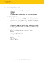
Place the grounding clamp between the fieldbus connectors by using a screwdriver in
such way that the clamp contacts the metal housing of the connectors.
a
The shielding of the fieldbus cables is connected to the grounding clip.
Fig. 25: Mounting the grounding clip
5.6.4
Grounding the device – mounting on a DIN rail
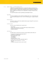
For mounting on a DIN rail with TBNN-S0-DRS connectors: Screw the enclosed metal
screw into the lower mounting hole of the TBEN-S module.
a
The shielding of the M8 flanges of the I/O level is connected to the reference potential of
the installation via the DIN rail and the connector.
a
With mounted grounding clip: The shielding of the fieldbus is connected to the reference
potential of the installation via the module grounding of the I/O level.

