


D301171 - IO-Link master 1108
3-7
Connection possibilities
3
Connection possibilities
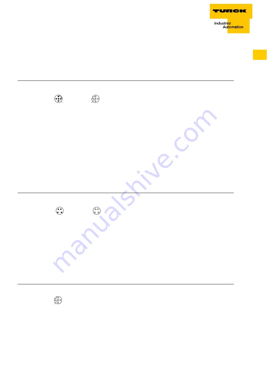
Fieldbus connection
PROFIBUS-DP connection
At the SDPX-IOL4-0001, the connection to PROFIBUS-DP is realized via two M12-connec-
tors.
Supply voltage
The connection of the supply voltage is done via 4-pole M8-connectors at each module.
operating voltage U
B
The 24 VDC operation voltage U
B
is used to supply the fieldbus (termination), the processor
logic, the IO-Link ports as well as the sensors.
The operation voltage is galvanically isolated from the fieldbus (ASIC).
load voltage U
L
The load voltage U
L
is not used in the module but only monitored and provided for eventual
transmission.
M12-connector for IO-Link
The connection of a maximum number of 4 IO-Link sensors is done via PIN 4 of each of the
4 M12-female connectors on the SPDX-IOL4-0001.
PIN 2 of each female connector can be used to connect simple pnp-inputs.
In case of more complex sensors, PIN 2 can for example be used as an input for a sensor
switching point.
Figure 5:
M12-connector
for PROFIBUS-
connection
Figure 6:
Pin assignment
M8-male and
M8-female
connector
Figure 7:
Pin assignment
of the M12-
female connec-
tors
w
v
4
1
3
2
5
4
1
3
2
5
C4
C5
1 = 5 VDC
2 = BUS-A
3 = GND
4 = BUS-B
5 = n.c.
1 = 5 VDC
2 = BUS-A
3 = GND
4 = BUS-B
5 = n.c.
3
1
4
2
1
3
2
4
w
v
1 = 24 VDC U
B
2 = 24 VDC U
L
3 = GND
4 = GND
C6
C7
4
1
3
2
5
v
C0...C3
1 = 24 VDC
2 = Input
3 = GND
4 = C/Q (IO-Link)
5 = n.c.