


10
ADVANCED FEATURES ON THE STRAIGHT WASTEGATE
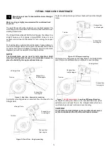
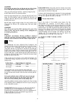
Water Cooling
Turbosmart’s Straight Gate is equipped with water cooling ports
to keep the wastegate cool in the most extreme conditions and
keep consistent actuator temperature.
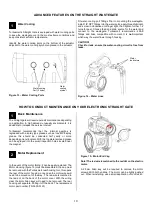
Identify the water cooling ports on the bottom of the actuator
adjacent to the water-cooling symbol engraved in the actuator.
Figure 13
– Water Cooling Ports
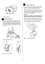
Fit water-cooling port fittings Prior to mounting the wastegate,
install 1/8” NPT fittings into the water ports, apply thread lubricant
and screw in clockwise until finger tight, then tighten further 1-2
turns for seal. Choose feed and drain source for the water and
connect to the wastegate. Turbosmart recommends -4SAE
fittings and hose compatible with coolant. It is
not
important
which way the water flows through housing.
CAUTION!
Check for leak, ensure the water-cooling circuit is free from
leaks.
Figure 14
– Water Lines
HOW TO CONDUCT MAINTENANCE ON YOUR ELECTRONIC STRAIGHT GATE
Basic Maintenance
The Straight gate will require periodic maintenance depending
on application. In high demand, unusually environments, it is
advisable to increase the service interval.
Turbosmart recommends that the internal gearbox is
regreased with a spray type grease such as Inox MX8 spray
grease this should be conducted half yearly or more
depending on environment. With the top plate removed grease
can be sprayed into the small inspection holes located near
the magnet.
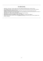
Motor Replacement
In the event of the motor failing, it can be easily replaced. The
Motor Housing (figure 15) must be dissembled, the cap must
be removed with the Turbosmart rear housing tool, this opens
the rear of the motor housing, once open the motor wires will
need to be moved out of the way . The red wire is matched to
the red dot on the back of the motor cover. With the wiring
clear the 4mm Allen keys will need to be removed. The rear
housing will separate. Pulling it off the back. The replacement
motor part number (TS-0550-3123)
Figure 15
– Motor End Cap
Note! The red wire is matched to the red dot on the electric
motor.
A 2.5mm Allen key will be required to remove the motor
screws. With both undone. The motor can be lightly pushed
out. When reinstalling, use a small application of Loctite 243
Water cooling
Port (2 holes)
1
3
Water
cooling
symbol
Water
feed/return
1
2


