Turbo Air Speed up the Pace of Innovation
Commercial
Refrigerator & Freezer
Service Manual
CAUTION!
PLEASE KEEP POWER
SWITCH ON BEFORE
OPERATING THIS EQUIPMENT
Please read this manual completely before attempting to install or operate this equipment!
www.turboairinc.com
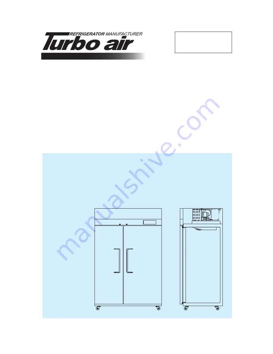
JRF-45
J Series
SOLID DOOR


