


6
Copyright 2003-2018 Tufin Software Technologies Ltd. |
T-510 Quick Start Guide
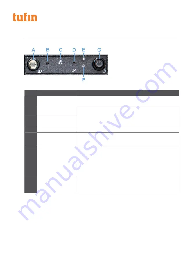
FRONT PANEL LEDS AND BUTTONS
All control buttons and status LEDs are located on the front of the appliance:
Figure 2-2: Front LEDs and buttons
ITEM
FEATURE
DESCRIPTION
A
System ID button with
integrated LED (green)
When pressed, it toggles the ID LEDs on the front and back of the
appliance.
B
Halt button
When pressed, it puts the server in a halt state so that the memory can
be downloaded for diagnostics
C
Onboard LAN LED
(green)
Indicates NIC activity for each of the two onboard network interfaces.
NIC activity for the
D
System cold-reset button
When pressed, it reboots the appliance.
E
HDD activity/ fault LED
(green/red)
Indicates HDD activity when green, or an HDD fault when red. This is an
aggregated indication for all hard disk drives in the system. Each hard
disk contains its own activity and fault indicators.
F
System status
(green/red)
Indicates system status as follows:
•
Steady green indicates system in standby or ready for operation.
•
Blinking green indicates degraded operation (e.g., power supply
nonredundancy, part of system memory mapped out by BIOS).
•
Blinking red indicates one or more non-critical fault conditions.
•
Steady red indicates one or more critical fault conditions.
G
Power button with
integrated LED (green)
When pressed, it toggles the system power. When continuously lit,
indicates the presence of power supply output power in the appliance.
The LED turns off when the power supply is turned off or the power
source is disrupted.
Table 2-2: Front LEDs and buttons


