920.1020.12
34
•
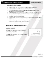
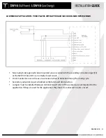
When wiring controls for use as a simultaneous pair, all required inputs need to
be sync’d (connected) between Door #1 and Door #2 (shown as dotted lines in
above diagram).
•
Example shown above: Push plates are connected to inputs 8, 10 and 11 at door
#1 and are connected via sync line to Door #2.
•
When using pairs of controls, N.C. inputs 12, 13 and 14 may be sync’d to each
other, OR each control may have it’s own jumpers installed. If any of these inputs
are required for the application, the jumper will be removed for the respective
input – in place of the jumper, a N.C. switching circuit will connected to Door #1,
and a sync line will be connected to Door #2.
•
For simultaneous pairs, Tucker Auto-Mation provides a dual harness for the On-
Off-Hold switch. Each plug-in connector for the control is wired in parallel to the
On-Off-Hold switch located in the header end-cap. One switch will control both
doors.
•
All control adjustments (speed & time delay) must be made independantly at
each control.
•
All dipswitches at each control must be set independantly and must match
between controls.
•
When using the TAP programmer, settings must be made independantly at each
control and must match between controls.
Summary of Contents for SW10
Page 11: ...920 1020 12 11 PUSH ARM ...
Page 27: ...920 1020 12 27 SETUP BUTTON FLASHING RED LED ...
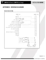
Page 33: ...920 1020 12 33 APPENDIX WIRING DIAGRAMS SIMULTANEOUS PAIRS ...
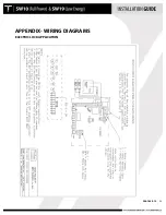
Page 35: ...920 1020 12 35 APPENDIX WIRING DIAGRAMS ELECTRIC LOCK APPLICATION ...
Page 36: ...920 1020 12 36 APPENDIX WIRING DIAGRAMS SW10 PAIR WITH BEA PARALLAX SYSTEM ...
Page 37: ...920 1020 12 37 APPENDIX WIRING DIAGRAMS SW10 Single Pair WIth BEA LZR Microscan Sensors ...


