background image

TT8900 OPT 

 Installation and Service Manual   

Page 16 of 41 

2.8


Supporting Cabinet Installation 

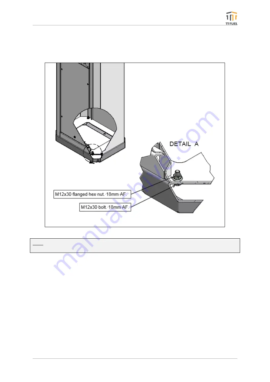
Once the plinth is installed, the supporting cabinet can be lifted onto the plinth and bolted down 
with the supplied fasteners as shown below. 


Note: Recommended tightening torque is approximately 40 Nm (30 foot-pound or 360 inch-
pound). 

2.9


Installing the TT8900 OPT inside the Optional Supporting Cabinet 

Once the supporting cabinet has been fastened to the plinth, follow these steps to install the 
TT8900 OPT into the supporting cabinet:  

1.


Using two people, one positioned each side of the supporting cabinet, lift the TT8900 

unit up 

to the level of supporting cabinet’s 

aperture and rest it on the internal supporting 

shelves inside the supporting cabinet.  

2.


Carefully slide the TT8900 OPT unit inside the supporting cabinet until it stops 

 at this 

point the hole-plugs in the bottom of the TT8900 OPT unit will have come up against the 
bottom shelf of the supporting cabinet.  

3.


Lifting the front of the TT8900 OPT and sliding it in will allow the hole plugs to clear and 

the unit to be fully inserted. 

Figure 3: TT8900 OPT Cabinet Tower Installation 

Summary of Contents for TT8900

Page 1: ...TT8900 Outdoor Payment Terminal Installation and Service Manual October 2021 TT8900 OPT shown as mounted inside optional supporting cabinet ...

Page 2: ...Rugged Purposeful Effective ...

Page 3: ...For any questions technical or otherwise please contact us ttfuel com support ttfuel com 61 8 8215 5000 For the latest documentation and product updates visit our Resource Centre ttfuel com resources ...

Page 4: ...y Holes 18 2 11 Connecting the Power Supply Unit to the AC Mains Power 18 2 12 Connecting the UPS Battery 19 2 13 Connecting the Cellular Network Antenna 19 2 14 Forecourt Connections 19 2 15 Description of Emergency Stop Interface 21 3 Configuration and Testing 22 3 1 T20 TSM Configuration 22 3 2 T20 IIM Configuration 23 3 3 Step by Step Configuration 24 3 4 Configuration Menu 24 4 Commissioning ...

Page 5: ...d received approval OPT accepts WEX Motorpass cards if merchant has applied for and received approval However some cards or account types may be declined or limited by restrictions put in place by the card issuer The customer should contact their card issuer bank if their card is declined or the transaction amount is limited to below what is acceptable for their circumstances 1 1 Key Information A...

Page 6: ...ion of discount cards to provide discounts to loyal customers Product Restrictions Support for product fuel restrictions on local cards accounts Forecourt Specifications Protocols Supports Supports NZPP PEC Gilbarco Dresser Wayne pump protocols No of Supported Hoses Supports up to 32 hoses on the forecourt ATG Interface Interfaces with Veeder Root OPW Holykell Senix PV4 Weldann and Windbell Foreco...

Page 7: ...es Transaction Management Inventory Management Event Analysis Scheduled Data Import Export to third party packages Software upgrade Audit Internal audit log which can be accessed by central back office server for post analysis of events General Specifications Environment 10C to 50C with 95 non condensing humidity PIN Pad IP65 Card Reader IP4X Electrical 230V AC 1A maximum UPS and power filter incl...

Page 8: ...ing TT Fuel s proprietary HBus communication bus system The TT8900 OPT incorporates the following key modules T20 System Control Module SCM Conceptually similar to the former T6 Controller this module is the next gen forecourt control unit consequently the brain of the TT8900 OPT T20 Terminal Support Module TSM Specific to the OPT this module combines the functionalities of CAS PSM and EIM T20 Int...

Page 9: ...ior to deployment by filling in the Offline Mode Application Form Offline Mode Description Online Only The only authorisation method accepted for any transaction is Online Mode Any Internet connectivity disruption will render the OPT unusable Retail 1 Total exposure is limited to the Total Offline Transaction Limit Exposure per Id is limited to the Transaction Number Limit multiplied by the Floor ...

Page 10: ...nts Document Title Document Source TT8900 OPT User Manual TT Fuel T20 Showcase Brochure TT Fuel AS1940 2017 Storage and Handling of Flammable and Combustible Liquids SAI Global AS NZS2229 2004 Fuel dispensing equipment for explosive atmospheres SAI Global AS NZS3000 2016 Electrical installations SAI Global NMI R 117Measuring Systems for Liquids Other than Water National Measurement Institute ...

Page 11: ...ermining what other standards may apply AS 3000 Wiring Rules AS 1940 The storage and handling of flammable and combustible liquids AS NZS 2430 3 2 Classification of hazardous areas Part 3 2 Examples of area classification Vehicle workshops vehicle parking fuel dispensing stations and aircraft hangars 2 3 Safety Issues This list is provided as a guide to some of the product specific safety issues t...

Page 12: ...not exhaustive and the site surveyor should also consider any other criteria that may come from the customer or from legislative requirements Needs to be installed outside of the applicable hazardous area Transponder Technologies recommend that the OPT is installed at least 1m outside the reach of any fuel dispensing nozzle even if this is further away from any dispenser than what the applicable s...

Page 13: ...ary to correctly mount wire and configure the unit 2 The TT8900 OPT with the optional supporting cabinet Supporting documentation is also included to aid operators in correctly assemble and wire the unit For instructions on how to correctly assemble and wire the TT8900 OPT inside the optional supporting cabinet refer to the following chapters 2 6 Optional Supporting Cabinet 2 7 Mounting Plinth for...

Page 14: ...installed inside a supporting cabinet designed and engineered to withstand the harsh Australian outback conditions The supporting cabinet is manufactured from powder coated 304 grade stainless steel For maritime environments there is an option for 316 grade stainless steel to be used Figure 1 TT8900 OPT Cabinet Dimensions ...

Page 15: ...t be fastened on top of the mounting plinth designed to support the full supporting cabinet s weight and provide the required stability The plinth should be fixed using 4 dyna bolts or other concrete fasteners through the four 18mm holes to a flat and level concrete surface that is sufficiently substantial Figure 2 TT8900 OPT Plinth Mounting Points ...

Page 16: ... steps to install the TT8900 OPT into the supporting cabinet 1 Using two people one positioned each side of the supporting cabinet lift the TT8900 unit up to the level of supporting cabinet s aperture and rest it on the internal supporting shelves inside the supporting cabinet 2 Carefully slide the TT8900 OPT unit inside the supporting cabinet until it stops at this point the hole plugs in the bot...

Page 17: ...below Do not tighten the bolts at this stage tighten by hand only 6 Pull the TT8900 OPT unit towards the front of the supporting cabinet until the mounting bolts prevent it from coming any further forward 7 While looking at the front of the TT8900 OPT ensure that the aluminium bezel is sitting square inside the supporting cabinet aperture and that the gap between the bezel and the side faces of th...

Page 18: ... the AC Mains Power TT8900 OPT has been greatly simplified now offering a much more robust and quicker way to connect it to the mains power Follow these steps to correctly connect your TT8900 OPT to the main power 1 Route the power cable from the customer s junction box inside the OPT using one of the far right cable entry holes conveniently located next to the PSU as shown in Figure 6 2 Connect t...

Page 19: ... s UPS 4 Switch ON its power button 2 13 Connecting the Cellular Network Antenna Follow these steps to connect the Cellular Network Antenna 1 After having secured the Cellular Network Antenna route its cable inside the OPT through one of its entry holes 2 Screw in the SNA connector ensuring it is finger tight 2 14 Forecourt Connections The TT8900 OPT comes standard with support for two PEC NZ pump...

Page 20: ...splaying the optional interface modules Gilbarco Email ATG Postec and the channel serial interface they are wired to marked in blue Secondary TT8900 OPTs have a slightly different label depicted in Figure 10 attached on the inside of their enclosure displaying the connection information Note For more information regarding a Primary OPT driving Secondary OPTs read chapter 1 4 Tandem Configurations ...

Page 21: ...to this event refer to AS 1940 2004 Clause 7 3 5 To facilitate compliance with this requirement the OPT has an interface SL7V5 which must be connected to a normally closed voltage free contact that opens when the emergency shut down system activates This will cause the OPT to generate an alert event which will in turn relay the alarm to the appropriate person or organisation via the T ALERT servic...

Page 22: ... the CAS Card is now managed by the T20 TSM module Everything from product grades to tank and pump configurations is now performed through the Internal Interface Module T20 IIM procedures covered in chapters 3 2 3 4 The T20 TSM comes pre set from the factory having the SW1 DIP switch already configured as required However in case the Pump ID needs to be changed consult the table in Figure 14 Figur...

Page 23: ...Symbol Meaning Pump Dispenser i Idle s Dispensing predelivery d Dispensing h Dispensing on hold o Dispensing post delivery u In use Postec only n Nozzle out on hold c Reserved for card sale x Pump offline Tank Gauge i Idle p Probe error e Format error parity etc r Out of range x Tank probe offline WAYNE OTI CAS i No nozzles present a One or more nozzles detected l Lost vehicle contact both nozzle ...

Page 24: ...4 can be taken either locally or remotely via a modem network connection Note 1 This is a six digit number that allows both local and remote access to the TT8900 OPT Note 2 Refer to Part 6 of NMI V 2 1 and NMI V 2 2 3 4 Configuration Menu To access the configuration menu Main Menu NO passcode Configuration Menu Note The factory default passcode is 000000 Menu items are shown next to a number By se...

Page 25: ...is option prints the shift report 2 NON RESETABLE Selecting this option prints the report 3 PRODUCT by date range requires START and END dates 4 CARD by date range requires START and END dates 2 TANKS Selecting this option prints the Tank s report 3 SETUP Selecting this option prints the Configuration Report 4 IDS Selecting this option prints a Cards Report TRANSACTIONS 5 BUFFER 1 WHOLE BUFFER sel...

Page 26: ...09 Aviation Jet Fuel JET A1 10 ADBLUE 11 Ethanol Blend E10 12 Ethanol E85 2 PRICE The price per litre for selected grade up to 3 decimal places x xxx 3 DENSITY Density of selected grade in Kilograms per Litre 1 decimal place xxx x 4 PRICE SIGN MAP Displays the Price Sign Pump assignation 3 4 4 System MENU SELECTION DESCRIPTION 1 PASSCODE This is a 6 digit number that allows both local and remote a...

Page 27: ...tion could supply up to three fuel products This number will appear on the icon on the video monitor screen 1 to 32 2 CHANL Enter 0 1 or 2 This number reflects the channel number that the pump is using The TT8900 OPT supports two channels 1 and 2 If the status of a pump is set to 0 the pump is not configured for use and will not appear on the video monitor 3 TYPE The type of pump being used 1 PEC ...

Page 28: ...the quantity of fuel added to that tank 0 to 99999 5 DIP L Used to manually enter the most recent dip stick volume reading for that tank 6 METER Used to manually enter the meter value for EVERY pump that uses the tank First enter Pump Number then enter pump s meter reading up to 9999999 7 SETUP 1 HI ALRM volume litres at which HIGH overflow alarm is triggered 2 LO ALRM volume litres at which a LOW...

Page 29: ...m 8 COMMS 1 TYPE select the type of ATG system VEGA VDR OPW or VEGH rare 2 CHANNEL Select comms channel 1 or 2 3 ID Assigns the ID number to be used on the selected channel 3 4 8 Groups MENU SELECTION DESCRIPTION 1 GROUP NUMBER x Up to 16 00 to 15 groups can be nominated for use by forecourt devices 2 IS xx TYPE For each group nominated a FUEL GRADE is assigned to that group or a pre allocated dev...

Page 30: ...eck that the emergency stop system operates and causes the OPT to display EMERGENCY STOP on the LCD screen Check that the T WEB can connect with the OPT 4 1 Fitting the Compliance Plate The OPT s compliance plate is pop riveted using the rivets supplied in the parts bag to the left side of the tower using the holes already drilled in the tower Note The holes may require re drilling as the powder c...

Page 31: ...e any servicing is done on the OPT Dangerous voltages exist under the yellow safety cover DO NOT REMOVE THE COVER The OPT has an internal uninterruptible power supply UPS Note Please follow the instructions detailed in chapter 2 3 General Maintenance from the complementary TT 8900 OPT User Manual in case the OPT needs to be switched off first power off the battery then the mains power The door ass...

Page 32: ... To obtain a test print press the Form Feed FF button on the side of the printer The test print can be removed by pulling the paper straight out with a little downward pressure The printer s internal cutting edge should leave a clean slightly serrated edge across the width of the paper Note should the paper advance without any test print check the orientation of the paper as it may be upside down ...

Page 33: ...sing the 10mm socket and spanner release the four anti vibration nuts that are holding the reader to the front panel Note that one of these also holds the cable clamp for the cable 5 Carefully remove the reader from the door 6 After replacing the reader carefully undo steps 4 1 7 To complete the installation please finish the pairing process Note Pairing is the process of exchanging security keys ...

Page 34: ...sitioned correctly over the mounting studs 7 Install the new PIN Pad into position 8 Secure the PIN Pad with original retaining nuts Give each mounting spacer an extra half turn so the gasket seals correctly tightening evenly across the unit ie left bottom then right top then left bottom etc 9 Undo STEP 3 4 10 Power up the unit the battery then the mains power 11 Close the OPT door 12 Wait for the...

Page 35: ...om the mains power 3 Remove the T20 SCM P1 P2 and P3 connector banks using a flat head screwdriver 4 Using the same flat head screwdriver pull out both orange tabs keeping the T20 SCM module attached to the DIN rail 5 Pull out the T20 SCM module 6 Install the new T20 SCM module undoing steps 4 1 Important Make sure to match the Setup SW1 dip switches to the old module 7 Once the front door is clos...

Page 36: ...P1 P2 P3 and P4 connector banks using a flat head screwdriver 4 Disconnect the Ethernet cable 5 Using the same flat head screwdriver pull out both orange tabs keeping the T20 TSM module attached to the DIN rail 6 Pull out the T20 TSM module 7 Install the new T20 SCM module undoing steps 4 1 Important Make sure to match the Setup SW1 dip switches to the old module 8 Once the front door is closed tu...

Page 37: ...T8900 OPT door using the commissioned key 2 Power off the UPS battery then disconnect the TT8900 OPT unit from the mains power 3 Remove the data cable from the T20 SCM module using a flat head screwdriver 4 While pushing the module down against the rail swing the bottom end towards you to release it 5 Install the new T20 IIM module undoing steps 3 1 6 Once the front door is closed turn on the powe...

Page 38: ...e UPS battery then disconnect the TT8900 OPT unit from the mains power 3 Locate the Cellular Router module and Disconnect the cellular network antenna from the Cellular Router s end Disconnect the Ethernet cable Disconnect the power cable 4 While pushing the module down against the rail swing the bottom end towards you to release it 5 Install the new Cellular Router by pushing the module down agai...

Page 39: ...y undoing steps 3 1 5 Important Adjust the output voltage to 26VDC 0 1 as shown in Figure 28 6 Once the front door is closed turn on the power and resume your TT8900 OPT activity 5 9 Replacing the UPS Battery In the unfortunate event the USP battery needs to be replaced follow these steps to complete the swap and resume normal operations 1 Open the TT8900 OPT door using the commissioned key 2 Powe...

Page 40: ... Improvement Documentation can become outdated over time especially as products evolve and TT Fuel seeks to continually update documentation accordingly Unintentional technical or typographical errors are periodically corrected in later revisions Disclaimer All endeavours have been made to ensure information contained in this document is correct and accurate at the time of release TT Fuel does not...

Page 41: ...ers to help them overcome challenges and manage risk Our excellence in technical listening and our focus on outcomes have allowed us to become proven innovative problem solvers We strive for durability simplicity and exceptional performance when designing our products and solutions Our flexible solution architecture allows us to help customers manage change in their business and industry We are cu...

Reviews: