background image

-9-

Before starting

(1)   Make sure once again that the product is of the correct voltage and frequency rating.


Using the product at other than rated voltage and frequency will not only 

lower its performance but may damage the product.


Conf rm the rated voltage and frequency on the model name plate.

(2)   Confirm the wiring, supply voltage, circuit breaker capacity, and motor insulation resistance.


Reference insulation resistance = 20 MΩ or greater


The reference insulation resistance (20MΩ or greater ) is the value when the pump is new or has been 
repaired. For the reference value after installation, see below at Maintenance and Inspection (p.11)

(3) The setting on the circuit breaker or other overload protector should be made in accord with the rated 

currency of the pump.


See the model name plate on the pump for its rated current.

(4)  When powering the pump with a generator, do not share the generator with other equipment. 

CAUTION

Note:

Note:

Note:

6 OPERATION

(2) If the direction is reversed, correct it using the countermeasure shown below.


Before changing the connections to correct the rotation, be sure to turn off 

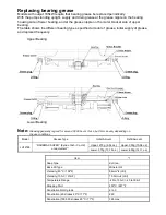
the power supply (circuit breaker), and make sure the impeller has stopped 

completely, to avoid electrical shock or shorting.

WARNING

Test operation


•  Never operate the pump while it is suspended in the air. The recoil may 

result in injury or other major accident.


•  Never start the pump when people are standing next to it. An electrical leak 

can result in electrical shock. 

(1)  Run the pump for a short time(1~2 seconds) to check the direction of rotation. The rotation is correct if 

the pump recoil direction is counter-clockwise.


Always perform the rotation check in air, not while the pump is submersed. 

Running the pump in reverse direction while submersed may damage the 

pump, resulting in electrical leakage or electrical shock. 

WARNING

CAUTION

COUNTERMEASURE


Interchange connections between any two of 

the three leads R, S, or T.

R S T

Example :

Interchanging 

phases S and T

(3)  Run the pump for a short time (3~10minutes) and confirm the following.


Using an ammeter(clamp-on type), measure the operating current at the U, V, and W phase leads on the 

terminal strip. 

COUNTERMEASURE


If the operating current exceeds the rated value, pump motor overload may be a cause. Make sure the pump 

has been installed under proper conditions as described in the section  on Installation(p.6)


Using an AC voltmeter(tester), measure voltage at the terminal strip.


Supply voltage tolerance: within ± 5% of rated voltage. 

COUNTERMEASURE


If the supply voltage is outside the tolerance, possible causes are the  power supply capacity or an inadequate 

extension cable. Look again at Electrical Wiring(p.7) and make sure the conditions are proper.


In case of very excessive vibration, unusual noise or odor, turn off the power 

immediately and consult with your nearest dealer or Tsurumi representative. 

Continuing to operate the pump under abnormal conditions may result in 

electrical shock, fire, or electrical leakage. 

(4)  If the test operation turns up no problems, continue with full operation.

CAUTION

Summary of Contents for LH Series

Page 1: ...roduct to another party always be sure to include this operation manual as well If this operation manual should become lost or damaged ask your nearest dealer or Tsurumi representative for another copy Every effort has been made to ensure the completeness and accuracy of this document Please contact your nearest dealer or Tsurumi representative if you notice any possible error or omission The cont...

Page 2: ...damage or the urgency of the precaution Note however that what is included under CAUTION may at times lead to a more serious problem In either case the categories pertain to safety related items and as such must be observed carefully WARNING CAUTION NOTE Explanation of Symbols PRECAUTIONS TO THE PRODUCT SPECIFICATIONS WARNING When transporting the product pay close attention to its center of gravi...

Page 3: ...o so may result in damage to nearby walls floors and other equipment PRECAUTIONS DURING TEST OPERATION AND OPERATION CAUTION WARNING Never start the pump if somebody is present in the pump sump If an electrical leakage occurs it can cause electrical shock When inspecting the pump be sure to turn off the power supply earth leakage circuit breaker etc so that the pump may not start accidentally Fail...

Page 4: ... where it was purchased or Tsurumi representa tive Improper repairs can result in electrical leakage electrical shock or fire Test operation stop OTHER PRECAUTION CAUTION Never use the product for potable water It may present a danger to human health Potable Water CAUTION Never insert a finger or any other object into the pump inlet holes Failure to observe this caution may lead to injury When the...

Page 5: ... Cable Mechanical Seal Leakage Sensor Electrode Shaft Upper Shaft Sleeve Middle Shaft Sleeve Upper Labyrinth Ring Lower Shaft Sleeve Lower Labyrinth Ring Oil Plug Oil Lifter Discharge Pipe Lifting Eye Bolt Upper Pump Casing Lower Pump Casing Suction Mouth Cathodic Protection Plate Impeller Oil Oil Plug Cabtyre Cable Strainer Stand Oil Casing Bearing Housing Mechanical Seal Leakage Sensor Electrode...

Page 6: ...den Water 0 40 C Pump Impeller Close Type Shaft Seal Double Mechanical Seal Bearing Ball Bearing Specifications Dry type Submersible Induction Motor 2 Pole Insulation Class F Protection System Built in Miniature Protector Leak Sensor Built in Electrode Turbine Oil VG32 Lubricant Connection to Piping JIS 10K Flange JIS 20K Flange Motor Example of nameplate 1 2 3 4 5 6 7 8 9 10 11 Submersible pump B...

Page 7: ... resistance tester AC voltmeter AC ammeter clamp on type Bolt and nut tighteners Power supply connection tools screwdriver or box wrench Please read also the instructions that come with each of the test instruments Note Maximum allowable water pressure Do not use at greater than the water pressure shown in the table CAUTION Model JIS20K 0 5MPa 5kgf cm2 JIS10K Flange Specification LH6110 JIS20K LH4...

Page 8: ... not collect in it 9 When performing pipe construction make sure welding sparks or paint do not contact the pump This pump is supplied without piping Use it with suitable piping material The tip of the hose discharge end should be located higher than the water surface If the end of the hose is submerged water may f low back to the pump when the pump is stopped and if the hose end is lower than the...

Page 9: ...ctrical leakage electrical shock or fire Do not allow the cabtyre cable leads to become wet Make sure the cable does not become excessively bent or twisted and does not rub against a structure in a way that might damage it CAUTION Grounding Do not use the pump without first grounding it properly Failure to ground it can lead to electrical shock from an electrical leak or pump malfunction Do not at...

Page 10: ...lectrical leak can result in electrical shock 1 Run the pump for a short time 1 2 seconds to check the direction of rotation The rotation is correct if the pump recoil direction is counter clockwise Always perform the rotation check in air not while the pump is submersed Running the pump in reverse direction while submersed may damage the pump resulting in electrical leakage or electrical shock WA...

Page 11: ...eavy vibration and malfunctioning 1 Miniature Protector This protector is embedded inside the motor coil If the coil should overheat for any reason bending of the bimetal of the miniature protector triggers a signal which in turn causes an extermal circuit in the starting console or control panel to shut off the motor current When the temperature returns to normal the protector is automatically re...

Page 12: ...ump back into service When the pump is left installed in water it should be run at regular intervals about once a week Note Interval Monthly EveryDay Yearly Inspection Item Every 2 to 5 years Measure operating current Measure insulation resistance Note If the insulation resistance has become notably lower than the precious inspection an inspection of the motor will be necessary Note Specialized kn...

Page 13: ... oil and other waste products should be disposed of by a qualif ied agent in accord with applicable local laws The oil plug packing and O ring should be replaced each time the oil is inspected or changed Note Inspecting Oil Remove the oil plug and tilt the pump to drain a small amount of oil If the oil is milky white or has water mixed in with it the mechanical seal may be faulty In this case the ...

Page 14: ...rts consult with your nearest dealer or Tsurumi representative Improper repairs can result in electrical leakage electrical shock fire or water leaks After reassembly always perform a test operation before resuming use of the pump Improper assembly will cause the pump to malfunction resulting in electrical shock or water leaks The procedure for disassembly and reassembly is shown here to the exten...

Page 15: ...fter attaching the impeller and again after assembly is completed check to make sure the impeller rotates smoothly and that is does not rub against the suction mouth Note Note Oil Lifter Round Head Screw Mechanical Seal Oil Casing Upper Pump Casing Lower Pump Casing O Ring O Ring O Ring O Ring O Ring O Ring O Ring O Ring Suction Mouth Suction Mouth Packing Oil Plug Key Grease Plug Impeller Adjusti...

Page 16: ...e the impeller impeller adjusting washer and the middle shaft sleeve from the shaft 6 Remove the upper pump casing Remove the hex nuts and spring washers then remove the upper pump casing from the pump and lift the upper shaft sleeve from the shaft 7 When absolutely necessary the mechanical seal can be removed by first removing the oil casing See also the manual that comes with the replacement mec...

Page 17: ...sure the impeller rotates smoothly and that is does not rub against the pump casing The mouth rings are press f it into the upper pump casing and the lower pump casing and the labyrinth rings are press f it into the upper pump casing and the middle pump casing so it is necessary to replace the related pump casing s together when worn Note Note Note Note Oil Lifter Round Head Screw Mechanical Seal ...

Page 18: ...1207B or equivalent on the middle pump casing and the lower pump casing when assembling the pump The place to be applied is the top part of each casing It is f illed with black in the drawing below Note Middle Pump Casing Lower Pump Casing ...

Page 19: ...e sure the cabtyre cable extension is the proper standard 3 Check the name plate and replace the pump 4 Remove debris from the strainer 5 Repair or replace the motor 6 Place the pump on a block or other base to prevent sand from being sucked into it 1 Impeller is clogged 2 Low voltage 3 Wrong power frequency 4 Extended operation with a clogged strainer 5 Faulty motor 6 Excessive sand is discharged...

Page 20: ...s Back to back Duplex Motor Specifications Dry type Submersible Induction Motor 2 Pole Insulation Class F Protection System Built in Miniature Protector Leak Sensors Built in Electrode and Float Lubricant Turbine Oil VG32 Connection to Piping JIS 10K Flange Standard specification 60Hz Model Bore mm Phase Starting Method Output kW Max Head m feet Max CAPACITY m3 min GPM Weight kg LH12185 300 3 Star...

Page 21: ...AND INSPECTION Oil inspection and Oil change When the pump is tilted for inspecting or changing the oil pay careful attention to the center of gravity and weight of the pump Inspecting Oil Remove the oil plug and tilt the pump to drain a small amount of oil If the oil is milky white or has water mixed in with it the mechanical seal may be faulty In this case the pump will need to disassembled and ...

Page 22: ...Bearing Lower Bearing Note Greasing generally is good for around 3 000 hours of use but this can vary depending on the use conditions Model Grease Type Initial Amount Refill Amount LH12185 RAREMAX SUPER Kyodo Yushi Co Ltd or equivalent 1 Upper 270g 9 52 oz Upper 300g 10 58 oz Lower 370g 13 15 oz Lower 400g 14 11 oz Item 1 Soap Type di Urea Base Oil Type Mineral Oil Viscosity 40oC 104oF 94mm2 s cSt...

Reviews: