background image

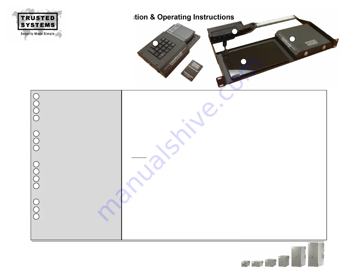
UserGuard Installation & Operating Instructions 


Trusted Systems, Inc. 
(410) 756-3300   
(800) 414-4203 
www.trustedsys.com 


1

2

3

4

For


installation,


please


refer


to


cabling


diagram


on


page


2.


1.


Feed


output


cabling


(8,


10


and


11)


in


through


the


cable


entry


portal


located


on


the


back


of


the


IPS


Container


and


connect


to


UserGuard


Control


Gateway


(1).


2.


Connect


14ft


Cat6


Ethernet


cable


(14)


to


back


of


Desktop


Module


“Kill


Box”


(2),


feed


into


IPS


Container


through


the


cable


entry


portal


and


connect


to


UserGuard


Control


Gateway


(1).


3.


Feed


2x


15ft


USB


extension


cables


(12)


already


connected


to


back


of


Desktop


Module


(2)


into


IPS


Container


through


the


cable


entry


portal


and


connect


to


USB


Power


Module


(4).


4.


Connect


1.5ft


USB


control


cable


(13)


between


USB


Power


Module


(4)


and


Intelligent


Gateway


(1).


5.


Connect


input


cables


(5,


6


and


7)


between


secure


PC/switch


and


Intelligent


Gateway


(1).


Note:


Do


NOT


connect


to


POE


device.


This


will


permanently


damage


the


UserGuard


Intelligent


Gateway.


6.


Secure


UserGuard


Rack


Mount


Kit


into


IPS


Container


rack


at


desired


location.


7.


Carefully


connect


the


micro


USB


cable


from


USB


Power


Module


(4)


to


Tablet


PC


(3).


Secure


micro


USB


cable


to


tablet


using


provided


strain


relief


clamp


and


cable


tie


as


shown


in


cabling


diagram


on


page


2.


8.


Plug


5v


power


adapters


from


USB


Power


Module


(4)


into


115V


power


source.


9.


Power


on


SIPR


PC/Laptop


and


UserGuard


Tablet


PC


(3).


The


Red


“OFF”


button


located


on


front


of


UserGuard


Control


Gateway


(1)


will


light


up.


10.


Manually


test


UserGuard


by


pressing


Blue


“ON”


button


located


on


front


of


UserGuard


Control


Gateway


(1).


Ensure


that


video,


USB


and


Ethernet


connections


are


active


and


video


output


settings


are


correct.


(Note:


Laptop


display


&


power


settings


may


need


to


be


adjusted


so


external


monitor


remains


active


when


laptop


is


closed.)


11.


Once


desktop


correctly


displays


and


connections


are


verified,


press


“Kill


Button”


located


on


front


of


Desktop


Module


(2).


12.


Now


activate


the


UserGuard


system


with


provided


CAC


card


by


following


the


“Operating


Instructions”


on


page


3.


Once


system


operation


has


been


verified,


remove


CAC


to


deactivate


the


system.


13.


Connect


9v


power


adapter


for


motion


sensor


to


back


of


Desktop


Module


(2)


and


plug


into


115V


power


source.


Switch


to


“ON”


position


and


verify


motion


sensor


operation.


14.


Secure


all


cables


to


white


cable


tie


mount


located


on


the


Rack


Mount


Kit


(4)


using


supplied


cable


ties.


Your


UserGuard


system


is now


fully


operational.


ENCLOSED


ITEMS:


INSTALLATION


INSTRUCTIONS


Intelligent


Gateway


Desktop


Access


Control


Module


Tablet


PC


(with


strain


relief


clamp)


Rack


Mount


Kit


(with


USB


Power


Module)


Input


Cables:


6ft


USB


cable


M

M


6ft


HDMI


cable


M

M


7ft


Cat6


Ethernet


cable


Output


Cables:


15ft


USB


extension


cable


M

F


4

port


USB


Hub


(with


power


adapter)


15ft


HDMI


cable


M

M


14ft


Cat6


Ethernet


cable


Control


Cables:


2x


15ft


USB


extension


cables


M

F


1.5ft


USB


cable


M

M


14ft


Cat6


Ethernet


cable


UserGuard


CAC


Cards


(5


total)


Cable


Ties


(10


total)


1


2


3


4


5


6


7


8


9


10


11


12


13


14


Summary of Contents for UserGuard

Page 1: ...The Red OFF button located on front of UserGuard Control Gateway 1 will light up 10 Manually test UserGuard by pressing Blue ON button located on front of UserGuard Control Gateway 1 Ensure that video USB and Ethernet connections are active and video output settings are correct Note Laptop display power settings may need to be adjusted so external monitor remains active when laptop is closed 11 On...

Page 2: ... 2 Tablet Strain Relief Clamp PIN PAD Trusted Systems IPS Container SIPR PC Laptop USB IN ETH IN HDMI IN HDMI OUT ETH OUT USB OUT KILL BOX CNTRL SIPR switch VOSIP SECURE VTC 1 2 3 4 5 6 7 8 9 10 11 12 13 14 8 10 11 12 14 SIPR token No POE AUX CNTRL CAC READER 5v 5v 9v ETHERNET to Laptop Crypto ETHERNET to VOSIP VTC ...

Page 3: ...UST RE ENROLL THE CARD BY FOLLOWING INSTRUCTIONS ON PAGE 4 OPERATING INSTRUCTIONS 1 If wrong PIN is entered or system does not activate remove CAC card from reader and wait approx 10 seconds before trying again This will allow the system to reset 2 The motion sensor auto timeout factory default is set to 30 seconds If system times out intermittently while user is present increase the timer setting...

Page 4: ...to aid with CAC PIN management on the UserGuard Tablet PC Up to 5 separate CAC PIN users can be enrolled on the system with one card for each Windows client account To enter a new CAC PIN credential use the Tablet touch screen to select a Windows client Trusted 1 through Trusted 5 and logon using administrator Windows password default password 7777 Be sure the CAC is not on the reader at this time...

Reviews: