background image

Support: 1-855-473-7449 or 1-408-943-4100                                      

                           Email: 

[email protected]

Page 2

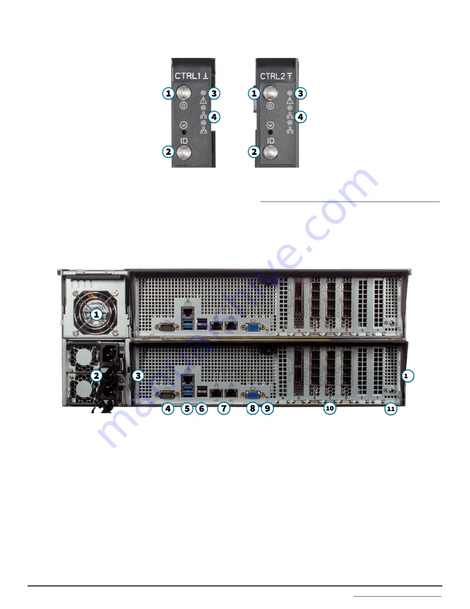
The front “ears” have indicators for power 

(1)

, locate ID 

(2)

, fault 

(3)

, and network activity 

(4)

. The fault indicator is on 

during the initial power-on self-test (POST) and off during operation. It also turns on if TrueNAS OS issues an alert. 

For details about software alerts and how to configure them, see 

https://www.truenas.com/docs/core/system/alert/


on the TrueNAS Documentation Hub.

The M-Series includes one or two TrueNAS controllers in an over-and-under configuration.

1.3  M-Series Back Panel

1. 

NVMe drive bays with fan and indicators. NVMe bays are active on all M-Series models 

except the M30

.

2. 

Power supplies 1 (bottom slot) and 2 (top slot)

3. 

IPMI Password sticker

4.  Serial port
5. 

1Gb Ethernet Out of Band Management port and USB 3.0 ports

6.  USB 2.0 ports
7. 

10Gb Ethernet ports

8. 

VGA monitor port

9. 

ID indicator

10. Expansion slots * (see section


“1.4  M-Series Expansion Slots”

)

11. 

TrueNAS


controller management port

12. 

TrueNAS controller serial number

1.2  Front Panel Indicators

2

Summary of Contents for M Series

Page 1: ...TrueNAS M Series Unified Storage Array Basic Setup Guide Version 3 31 ...

Page 2: ... Contents 1 Become Familiar with the M Series 1 1 1 Unified Chassis Design 1 1 2 Front Panel Indicators 2 1 3 M Series Back Panel 2 1 4 M Series Expansion Slots 3 2 Prerequisites 4 2 1 Handling 4 2 2 Static Discharge 4 3 M Series Rail Kit Assembly 5 3 1 Separate Cabinet Rails from Rack Rails 5 3 2 Mount Cabinet Rails 5 3 3 Mount the Rack Rails 5 3 4 Mount the Unit in the Rack 6 4 Install Drive Tra...

Page 3: ...C13 to NEMA 5 15P power cords 2 IEC C13 to C14 cords and a set of velcro cable ties Hardware for mounting the system in a rack DB9 to 3 5mm serial cable 1 Become Familiar with the M Series Bezel Up to 24 drive trays or air baffles depending on the number of drives purchased with the system The 3rd Generation TrueNAS M Series systems have a unified chassis design that allows customers to upgrade th...

Page 4: ... TrueNAS Documentation Hub The M Series includes one or two TrueNAS controllers in an over and under configuration 1 3 M Series Back Panel 1 NVMe drive bays with fan and indicators NVMe bays are active on all M Series models except the M30 2 Power supplies 1 bottom slot and 2 top slot 3 IPMI Password sticker 4 Serial port 5 1Gb Ethernet Out of Band Management port and USB 3 0 ports 6 USB 2 0 ports ...

Page 5: ...E Slot F M30 NIC or FC N A NTB N A Internal SAS Secondary NIC M40 NIC N A NTB External SAS Internal SAS x4 NVMe Riser NIC2 or FC M50 NIC1 External SAS1 NIC2 or FC External SAS2 NTB Internal SAS M60 NIC1 External SAS1 External SAS3 NIC2 or FC External SAS2 NTB Internal SAS 1 4 1 M30 Controller Expansion Slots 1 4 2 M40 Controller Expansion Slots 1 4 4 M60 Controller Expansion Slots 1 4 3 M50 Contro...

Page 6: ... chassis with your bare hand to dissipate static electricity in your body before touching any internal components including components not yet installed in the system Using an anti static wristband and grounding cable is another option 4 Store all system components in anti static bags You can find more preventative tips and details about ESD at https www wikihow com Ground Your self to Avoid Destr...

Page 7: ...the rail to the system with three M4x3 2mm screws Repeat this process on the other side 3 2 Mount Cabinet Rails The rack rails are installed in the bottom 2U of the total 4U of reserved rack space The inner rack rail must be unlocked and retracted before installing the rail in the rack Rotate the release lever on the back of the inner rail clockwise as shown on the arrow label 1 Push the inner rai...

Page 8: ...ase tabs on both cabinet rails towards the front of the system 1 while pushing the unit into the rack Push the chassis into the rack until it is flush with the front of the rack 2 To anchor the unit in the rack insert a long M5 screw through the retention port on each ear The screw hole is behind a small door on each ear Place the rail in the rack with the front end towards the front of the rack al...

Page 9: ...baffle Each drive bay in the chassis has two indicator lights to the right of the tray The upper light is blue when the drive is active or a hot spare The lower light is solid red if a fault has occurred Press the silver button on the drive tray to open the latch Carefully slide the tray into a drive bay until the right side of the latch touches the metal front edge of the chassis then gently swin...

Page 10: ...onnected to the M Series power on the expansion shelves and wait at least two minutes before connecting power cables to the M Series To set up SAS between your TrueNAS system and Expansion Shelves cable the first port on the first TrueNAS Controller to the first port on the first Expansion Shelf Controller High Availability systems require another cable from the first port on the second TrueNAS Co...

Page 11: ...k port labels in section 1 2 Front Panel Indicators on page 2 as needed Network ports are preconfigured to customer specifications before shipment 5 3 Power Cord Connect a power cord to the back of one power supply pressing it into the plastic clamp and pressing on the tab to lock it in place Repeat the process for the second power supply and cord After both power cords have been connected to the M ...

Page 12: ...is not required for operation To attach the bezel slide the right side of the bezel into the attach ment points on the right ear 1 Push the left side of the bezel into the left ear latch until it locks in place 2 To remove the bezel push the left ear release tab away from the bezel to release Swing the bezel out to remove ...

Page 13: ...ond TrueNAS Controller M Series systems with only one TrueNAS controller have an internal shipping brace that must be removed before adding a second TrueNAS controller Remove the cover plate thumbscrew 1 and controller slot cover 2 Warning To avoid the potential for data loss iXsystems must be contacted before replacing a controller or upgrad ing to High Availability See section 10 Contacting iXsy...

Page 14: ...ft the black release handle to lock the TrueNAS controller in place 2 Tighten the thumb screw to lock the handle 7 3 TrueNAS Controller Removal Unlock the TrueNAS controller handle by turning the thumb screw counter clockwise until it releases the handle 1 Do not pull or press on any portion of the TrueNAS controller except the black release handle Pull the black release handle down 2 to release t...

Page 15: ...the web user interface Your system has the optimal BIOS and IPMI firmware out of the box DO NOT UPGRADE your system s BIOS and IPMI firmware unless directed to by iXsystems support 8 1 Default Credentials The TrueNAS web interface uses default credentials for first time logins Username root Password abcd1234 After logging in with these default credentials change the root account password to a new ...

Page 16: ...old Level Support only US only toll free 1 855 499 5131 International 1 408 878 3140 International calling rates will apply The TrueNAS Documentation Hub has complete software configuration and usage instructions It is available by clicking Guide in the TrueNAS web interface or going directly to https www truenas com docs Additional hardware guides and articles are available in the Hardware sectio...

Reviews: