background image

10RStager Installation and Operational Manual 10R80 Transmissions

Rev C

Note: The following instructions are for 8 cylinder 10R80 Automatic Transmission installations for 2018 and
newer model years. Contact True Motorsports for other 10R80 configurations.

This manual will outline the wiring of the 10RStager. Ensure that each connection is a reliable connection that
will not cause any intermittent behavior on the signals. For power connections to the 10RStager, ensure that
the power source is a switched ignition source that powers up when you key on and that it has an appropriately
sized fuse for the circuits connected. The 10RStager consumes less than 0.5 Amps during operation.

The 10RStager must be wired per the instructions outlined in this document and is designed to work for

first

gear and second gear launch setups

. The wiring for the second gear Transbrake is slightly different than the

first gear and also requires an ECU tune that enables second gear launches. The 10RStager will not operate
without interfacing to the transmission and brake pedal wiring. The brake pedal wiring must be wired to prevent
accidental engagement of the transbrake. Note that the foot brake pedal must be engaged prior to pressing the
Transbrake button to engage the Transbrake.

Perform the installation in the following order:

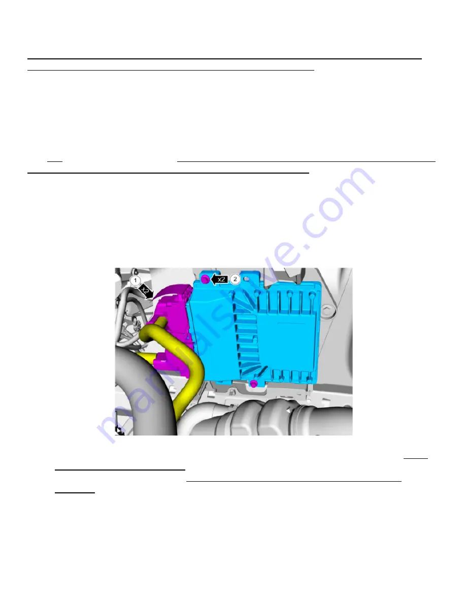
1. Turn the ignition off, open the hood

and disconnect the battery

.  Locate the vehicle PCM (Powertrain

Control Module).  This should be under the hood near the front passenger side.

2. Locate and install the 10RStager control box in a location that is within the cab of the vehicle. Do not

locate this device in the engine bay.  Follow the wiring diagram instructions below and on the following
pages. When wiring up this device, ensure that best practices are followed while wiring up the
10RStager.  It is recommended that each connection be soldered and heat shrink applied.

3. The instructions for wiring the 10RStager will be outlined on the following pages.  The diagram shown

on pages 2 and 3 should be used as an overall system wiring diagram. Follow the instructions outlined
in item 4 below, to wire the 10RStager per the following wiring diagrams:

Page 1

Summary of Contents for 10RStager

Page 1: ...RStager will not operate without interfacing to the transmission and brake pedal wiring The brake pedal wiring must be wired to prevent accidental engagement of the transbrake Note that the foot brake pedal must be engaged prior to pressing the Transbrake button to engage the Transbrake Perform the installation in the following order 1 Turn the ignition off open the hood and disconnect the battery...

Page 2: ...n Switch Power wire Green Red Connect the Tan Wire to the SSF wire Blue Grey that is connected to the 10R80 Connect the Orange Wire to the SSC wire Grey Orange that is connected to the 10R80 Connect the Yellow Wire to the SSB wire Green Brown that is connected to the 10R80 Note The signal at the light blue wire can be used to initialize a 2 step or other devices If a 2 step interface is needed att...

Page 3: ...nnect the Light Green Wire to the PCM side Connect the Pink Wire to the Brake Pedal Position Switch Signal wire Violet White Connect the White Wire to the Brake Pedal Position Switch Power wire Green Red Connect the Tan Wire to the SSF wire Blue Grey that is connected to the 10R80 Connect the Yellow Wire to the SSB wire Green Brown that is connected to the 10R80 Page 3 ...

Page 4: ... side of the engine Disconnect the Top PCM connector Run six wires with SSB SSC and SSF as part of the naming convention out to the PCM Transmission connector located in the engine compartment Run through the passenger side firewall grommet Page 4 ...

Page 5: ...5 On the PCM connector remove at least 6 8 inches of the black tape so that you can access the wires Page 5 ...

Page 6: ...6 Identify the SSF SSC and SSB solenoid wires so that the 10RStager can be inserted into this interface FIRST GEAR ONLY Page 6 ...

Page 7: ... ONLY The SSB SSC first gear only and SSF signals will pass through the 10RStager during normal operation When the Transbrake is activated the 10RStager will manipulate the solenoids to create a Transbrake Page 7 ...

Page 8: ...e 10RStager wire harness connect the Red power wire to a switched 12V power source so that it will only turn ON when Ignition Power is applied or when a dedicated switch is used The 10RStager consumes less than 0 5 Amps of current while under maximum load Connect the Black wire to a clean battery ground connection as a poor chassis ground connection could damage the electronics or result in inadeq...

Page 9: ...he Transbrake button Below is a guide to assist you in finding the best settings for your vehicle Step 1 Start with the Force to the 7 o clock position and Speed near the 10 o clock position Step 1 Step 2 Step 3 Step 4 Set Speed to 11 o clock and Force to 7 o clock Press and hold the Bump Button If NO movement Increase the Force 1 click Press and hold the Bump Button If NO movement set Speed to 2 ...

Reviews: