background image

FKR-EU

1

K4 – 1.1 – 21

03/2017 – DE/en

Attachments

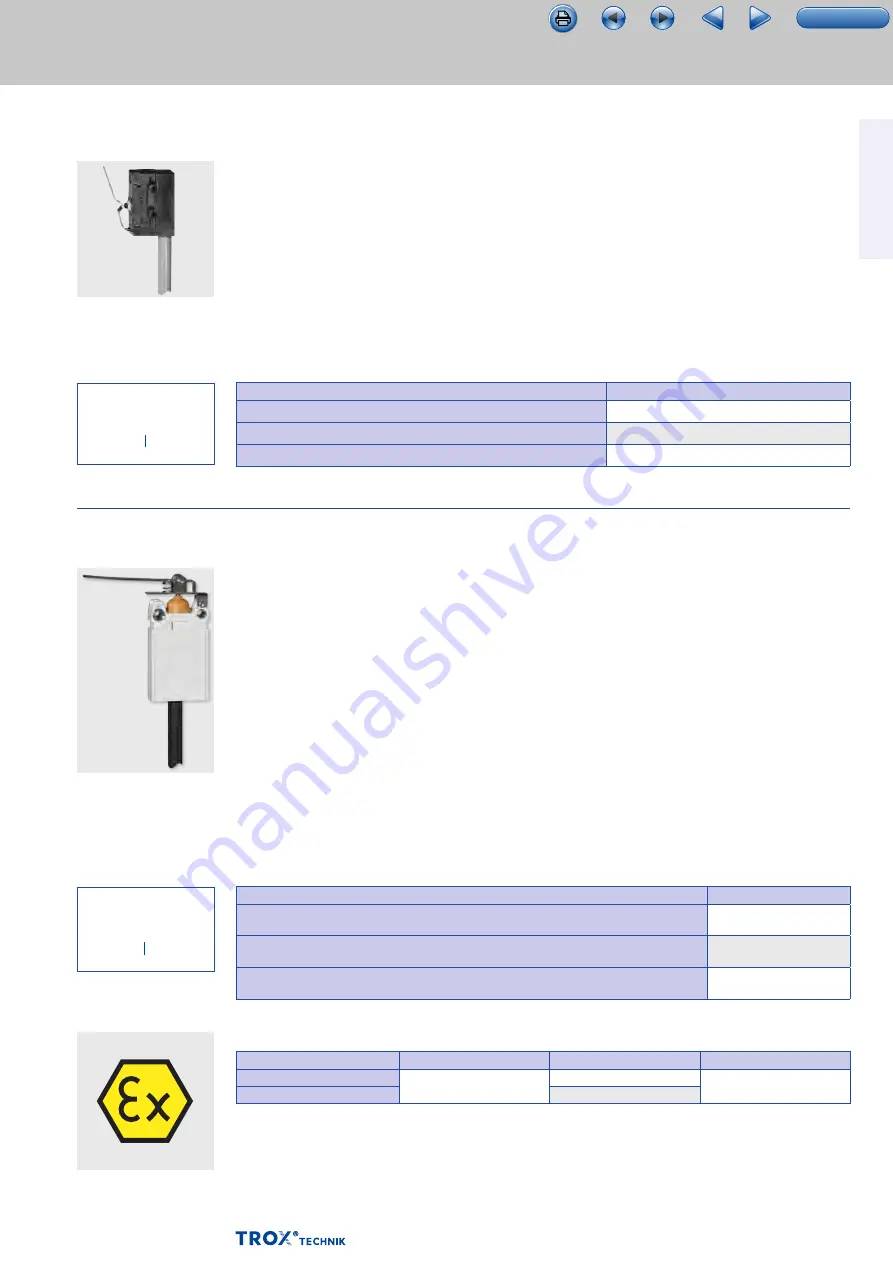
Limit switch

Limit switch

Limit switch (explosion- 

proof)

FKR-EU with limit switch

–  Limit switches with volt-free contacts

  enable  the damper blade position indication.

–  Up to the maximum switch rating,

  relays or  indicator lights for fire alarm

  systems can be  used

–  One limit switch each is required for damper  

blade positions OPEN and CLOSED

–  Fire dampers with a fusible link can be supplied  

with one or two limit switches;

  the switches can  also be fitted later

–  For technical data and wiring examples

  refer to  the additional technical leaflet 

'Attachments for  fire dampers'

FKR-EU with explosion-proof limit switch

–  According to declaration of conformity  

TÜV 13 ATEX 128437 X explosion-proof limit  

switches with volt-free contacts can indicate  

the damper blade position

–  Up to the maximum switch rating,

  relays or  indicator lights for fire alarm

  systems can be  used

–  The limit switches must be connected

  in a  separately approved casing with

  a type of  protection according to EN 60079-0

–  One limit switch each is required for damper  

blade positions OPEN and CLOSED

–  Fire dampers with a fusible link can be supplied  

with one or two limit switches;

  the switches can  also be fitted later

–  For technical data and wiring examples

  refer to  the supplementary technical leaflet  

"Attachments for fire dampers" and to the  

supplementary operating manual

  "Explosion- proof fire dampers, Type FKR-EU"

Description

For detailed information  

on limit switches see  

Chapter 1.2

Description

For detailed information  

on limit switches see  

Chapter 1.2

  /  

Z01


  /  

Z02


  /  

Z03


Order code detail

  /  

Z01EX


  /  

Z02EX


  /  

Z03EX


Order code detail

Attachments

Order code

Limit switch for damper blade position "CLOSED"

Z01

Limit switch for damper blade position OPEN

Z02

Limit switches for damper blade positions  CLOSED and OPEN

Z03

Attachments

Order code

Limit switch (explosion-proof) for damper blade  position CLOSED

Z01EX

Limit switch (explosion-proof) for damper blade  position OPEN

Z02EX

Limit switches (explosion-proof) for damper blade  positions CLOSED and OPEN

Z03EX

Z01EX – Z03EX

–  Zones 1, 2: Gases, mists and vapours

–  Zones 21, 22: Dusts


ATEX certification

ATEX areas of application for the FKR-EU 

Release mechanism

Marker

Ambient temperature Maximum airflow velocity

Fusible link

II 2D c T80 °C

II 2G c IIC T6

–40 to 40 °C

8 m/s

Fusible link and limit switch

–20 to 40 °C

TOC

Summary of Contents for FKR-EU

Page 1: ... sizes 315 800 mm Low differential pressure and sound power level Flanges as an option Explosion proof construction ATEX as an option Optional stainless steel casing or powder coated casing for increased corrosion protection Integration into the central BMS with TROXNETCOM Optional equipment and accessories Electric actuator 24 V 230 V Release temperature 72 95 C Duct smoke detectors FKR EU 1 1 FK...

Page 2: ... 1 1 25 Free area and resistance coefficient 1 1 26 Dimensions and weight FKR EU 1 1 27 Dimensions and weight FKR EU Z4 1 1 28 Dimensions and weight FKR EU ZEX 1 1 29 Dimensions and weight FKR EU FL 1 1 30 Dimensions and weight FKR EU FL Z4 1 1 31 Dimensions and weight FKR EU FL ZEX 1 1 32 Flange holes 1 1 33 Specification text 1 1 34 Basic information and nomenclature 1 3 1 Page K4 1 1 2 Variants...

Page 3: ...ilding inspectorate licence Z 56 4212 991 for fire resistance properties Complies with the requirements of EN 15650 Tested to EN 1366 2 for fire resistance properties Hygiene complies with VDI 6022 part 1 07 2011 VDI 3803 02 2010 DIN 1946 part 4 12 2008 and EN 13779 09 2007 Corrosion protection according to EN 15650 in connection with EN 60068 2 52 Closed blade air leakage to EN 1751 class 4 Casin...

Page 4: ...nance The functional reliability of the fire damper must be tested at least every six months this has to be arranged by the owner of the ventilation system functional tests must be carried out in compliance with the basic maintenance principles stated in EN 13306 and DIN 31051 If two consecutive tests one 6 months after the other are successful the next test can be conducted one year later A funct...

Page 5: ...tems by a fusible link The release mechanism is accessible and can be tested from the outside Both regular limit switches and explosion proof limit switches are available for zones 1 and 2 gases mists vapours and for zones 21 and 22 dusts to indicate damper blade positions Function Construction with fusible link K4 1 1 5 Schematic illustration of FKR EU FL with fusible link Casing Damper blade wit...

Page 6: ... fails the damper closes power off to close Motorised fire dampers can be used to shut off ducts The torque of each actuator is sufficient to open and close the damper blade even while the fan is running The spring return actuator is fitted with limit switches that can be used for capturing the damper blade position Function Construction with spring return actuator K4 1 1 6 Schematic illustration ...

Page 7: ...potentially explosive atmospheres The ambient temperatures and types of release and actuation specified in the technical data are binding RedMax Zone 2 Gases mists and vapours Zone 22 Dusts ExMax Zones 1 2 Gases mists and vapours Zones 21 22 Dusts Function Construction with spring return actuator explosion proof K4 1 1 7 ATEX certification Type of actuation Release mechanism Marker Ambient tempera...

Page 8: ...unplanned may cause damage to the fire damper or lead to corrosion If this fire damper is used in Germany Do not use it as an air transfer damper Do not use it in extract air systems in commercial kitchens A class of performance up to EI 120 ve ho i o S can only be achieved with ducts connected on both ends or with a duct on one end and a cover grille on the other end Essential characteristic fire...

Page 9: ...terials fibre reinforced gypsum or fire rated calcium silicate boards d 130 mm Distance between casings 40 mm Distance to load bearing structural elements 40 mm Timber stud wall also timber panel constructions and timber frames Gypsum bonded or cement bonded panel materials fibre reinforced gypsum or fire rated calcium silicate boards d 130 mm Installation kit TQ Timber stud wall also timber panel...

Page 10: ...ments 40 mm Metal support structure Additional safety board Gypsum bonded or cement bonded panel materials fibre reinforced gypsum or fire rated calcium silicate boards Cladding on one side with reinforcing board 90 mm without metal support structure Gypsum bonded or cement bonded panel materials fibre reinforced gypsum or fire rated calcium silicate boards Cladding on one side d 50 mm Distance to...

Page 11: ... dampers Correct use FKR EU 1 K4 1 1 11 Installation orientation Installation orientation with horizontal ducts FKR EU and FKR EU FL Release mechanism mechanical or spring return actuator 03 2017 DE en TOC ...

Page 12: ...n DE Germany Other destination countries upon request Nominal size mm 315 355 400 450 500 560 630 710 800 Accessories 1 No entry none TQ Installation kit construction with spigots Accessories 2 No entry none S0 AS Attachments Z00 ZEX4 W can be combined with all constructions and but not with attachments ZEX1 ZEX4 TQ cannot be combined with FKR EU FL Order code Order example FKR EU 1 DE 500 SS ZL09...

Page 13: ...er plate of the installation kit made of galvanised sheet steel and powder coated silver grey RAL 7001 when used with powder coated 1 and stainless steel 2 dampers Note For further information relevant to design in particular information on installation situations please refer to the operating and installation manual Description K4 1 1 13 Technical data Accessories 1 Order code Square installation...

Page 14: ...pectorate licence Z 6 50 2031 Materials and surfaces Cover grilles made of galvanised sheet steel and powder coated silver grey RAL 7001 when used with powder coated 1 and stainless steel 2 dampers Note For further information relevant to design in particular information on installation situations please refer to the operating and installation manual Description A0 0A AS SA Order code detail Techn...

Page 15: ... wire width 2 mm Extension piece 03 2017 DE en Extension piece and cover grille are supplied factory assembled Cover grille for FKR EU FL 175 370 Cover grille mesh aperture 15 mm 15 mm wire width 2 mm grille thickness approx 1 mm Extension piece Cover grille for FKR EU FL with extension pieces 175 370 175 Cover grille mesh aperture 15 mm 15 mm wire width 2 mm grille thickness approx 1 mm Extension...

Page 16: ...are supplied separately and can are fixed by others Flexible connectors are also available separately Materials and surfaces Flexible connectors made of galvanised steel FKR EU FL only and fibre reinforced plastic Fire resistance properties to 4102 B2 Extension piece made of galvanised sheet steel and powder coated silver grey RAL 7001 when used with powder coated 1 and stainless steel 2 dampers N...

Page 17: ...mm Flexible connector for FKR EU 215 Flexible connector Extension piece flexible length 100 mm when installed Flexible connector for FKR EU with extension pieces 215 175 Flexible connector Extension piece flexible length 100 mm when installed Flexible connector for FKR EU FL 180 170 Flexible connector Extension piece flexible length 100 mm when installed TOC ...

Page 18: ... be approx 50 mm Flexible connector for FKR EU FL with extension pieces 180 170 175 370 Flexible connector Extension piece flexible length 100 mm when installed Flexible connector for FKR EU 200 flexible length 100 mm when installed Flexible connector for FKR EU FL 180 n 9 5 flexible length 100 mm when installed 03 2017 DE en TOC ...

Page 19: ...uations please refer to the operating and installation manual Description Technical data When using cover grilles or flexible connectors extension pieces are required for some nominal sizes The distance a between the open damper blade and the cover grille or circular spigot should be approx 50 mm FKR EU dimensions mm Nominal size 315 355 400 450 500 560 630 710 800 x 270 250 230 200 175 145 110 70...

Page 20: ...FKR EU 1 K4 1 1 20 The distance a between the open damper blade and the cover grille or circular spigot should be approx 50 mm Extension piece for FKR EU L 175 370 55 Extension piece for FKR EU FL L 175 370 n 9 5 A 03 2017 DE en TOC ...

Page 21: ... positions OPEN and CLOSED Fire dampers with a fusible link can be supplied with one or two limit switches the switches can also be fitted later For technical data and wiring examples refer to the supplementary technical leaflet Attachments for fire dampers and to the supplementary operating manual Explosion proof fire dampers Type FKR EU Description For detailed information on limit switches see ...

Page 22: ...losive atmospheres If the supply voltage fails or with thermoelectric release the damper closes power off to close Fire dampers with spring return actuators can be functionally checked OPEN CLOSED OPEN Two integral limit switches with volt free contacts enable the damper blade position indication OPEN and CLOSED The electrical connection is made in the explosion proof terminal box Release temperat...

Page 23: ...me during functional testing The voltage 24 V DC for the module and the actuator is supplied via the two wire AS i flat cable Function display operation 4 inputs 2 outputs FKR EU with spring return actuator explosion proof and TROXNETCOM The AS interface is a global standard bus system according to EN 50295 and IEC 62026 2 It enables the integration of different components modules into a network r...

Page 24: ... 78 6 125 For airflow velocities from 1 20 m s Independent of the airflow direction Supply voltage 230 V AC 50 60 Hz or 24 V DC with voltage monitoring module VWM upon request Volt free signal and alarm relays Integral signal lamps Contamination level indicator Automatic adjustment of alarm threshold Long service life Temperature range 0 60 C RM O VS D Duct smoke detector for fire dampers and smok...

Page 25: ...0 2040 2940 400 700 1000 2500 3610 450 820 1180 2940 4240 500 980 1410 3530 5080 560 1190 1710 4280 6160 630 1450 2090 5230 7520 710 1780 2560 6400 9210 800 2170 3130 7810 11250 Given data Quick sizing Volume flow rate 3600 m h FKR EU 400 Sound power level 45 dB A The Easy Product Finder allows you to size products using your project specific data You will find the Easy Product Finder on our websi...

Page 26: ...rea and resistance coefficient FKR EU 1 K4 1 1 26 Nominal size A m ζ 315 0 069 0 44 355 0 089 0 34 400 0 114 0 26 450 0 140 0 21 500 0 175 0 17 560 0 222 0 13 630 0 285 0 10 710 0 365 0 08 800 0 468 0 06 03 2017 DE en TOC ...

Page 27: ...ns mm Weight kg Nominal size DN 315 355 400 450 500 560 630 710 800 ØD 314 354 399 449 499 559 629 709 799 Weight 6 8 7 3 8 5 14 1 16 4 18 21 3 25 7 28 6 FKR EU with spigot and fusible link 550 420 370 50 50 Ø D 70 150 Illustration shows nominal sizes 315 400 mm Keep clear to provide access to the release mechanism TOC ...

Page 28: ...g Nominal size DN 315 355 400 450 500 560 630 710 800 ØD 314 354 399 449 499 559 629 709 799 Weight 8 2 8 7 9 9 16 7 19 20 6 23 9 28 3 31 3 FKR EU with spigot and spring return actuator 550 420 370 50 50 ØD 70 150 Illustration shows nominal sizes 315 400 mm Keep clear to provide access to the spring return actuator 03 2017 DE en TOC ...

Page 29: ...nsions mm Weight kg Nominal size DN 315 355 400 450 500 560 630 710 800 ØD 314 354 399 449 499 559 629 709 799 Weight 12 12 14 19 21 23 26 31 34 FKR EU with spigot and explosion proof spring return actuator Illustration shows nominal sizes 450 800 mm 550 420 50 50 Ø D 93 166 370 200 Keep clear to provide access to the spring return actuator TOC ...

Page 30: ...mensions mm Weight kg Nominal size DN 315 355 400 450 500 560 630 710 800 ØD 314 354 399 449 499 559 629 709 799 Weight 6 8 7 3 8 5 14 1 16 4 18 21 3 25 7 28 6 FKR EU with flange and fusible link 495 395 342 Ø D 70 150 Illustration shows nominal sizes 315 400 mm Keep clear to provide access to the release mechanism TOC ...

Page 31: ...mm Weight kg Nominal size DN 315 355 400 450 500 560 630 710 800 ØD 314 354 399 449 499 559 629 709 799 Weight 8 2 8 7 9 9 16 7 19 20 6 23 9 28 3 31 3 FKR EU with flange and explosion proof spring return actuator 495 395 Ø D 70 150 342 Illustration shows nominal sizes 450 800 mm Keep clear to provide access to the spring return actuator TOC ...

Page 32: ...m Weight kg Nominal size DN 315 355 400 450 500 560 630 710 800 ØD 314 354 399 449 499 559 629 709 799 Weight 12 12 14 19 21 23 26 31 34 FKR EU with flange and explosion proof spring return actuator Illustration shows nominal sizes 450 800 mm 93 166 200 495 395 Ø D 342 Keep clear to provide access to the spring return actuator 03 2017 DE en TOC ...

Page 33: ...ns Nominal size DN 315 355 400 450 500 560 630 710 800 ØD mm 314 354 399 449 499 559 629 709 799 ØD mm 352 392 438 488 538 600 670 750 840 A mm 31 31 31 36 36 36 36 36 36 α 45 45 45 45 45 30 30 30 22 5 No of holes 8 8 8 8 8 12 12 12 16 FKR EU FL flange holes Ø D 495 A Ø D α Ø 9 5 TOC ...

Page 34: ...ation to EN 13501 3 up to EI 120 ve ho i o S Building inspectorate licence Z 56 4212 991 for fire resistance properties Complies with the requirements of EN 15650 Tested to EN 1366 2 for fire resistance properties Hygiene complies with VDI 6022 part 1 07 2011 VDI 3803 02 2010 DIN 1946 part 4 12 2008 and EN 13779 09 2007 Corrosion protection according to EN 15650 in connection with EN 60068 2 52 Cl...

Page 35: ...7 Impregnated damper blade 1 7 Powder coated casing RAL 7001 and impregnated damper blade 2 7 Stainless steel casing and impregnated damper blade W With fusible link 95 C only for use in warm air ventilation systems DE Germany 315 355 400 450 500 560 630 710 800 Accessories 1 No entry none Accessories 2 No entry none Attachments W can be combined with all constructions and but not with attachments...

Page 36: ...s can be determined quickly and precisely using the Easy Product Finder design programme Circular fire dampers Nominal size mm Diameter of the fire damper L mm Length of the fire damper Δpst Pa Static differential pressure v m s Airflow velocity based on the upstream cross section B H or diameter Principal dimensions Nomenclature Sizing with the help of this catalogue Wiring Colour codes according...

Reviews: