background image

AWC7813 motion controller user manual

WWW.SZTROCEN.COM

45

details

4.1 what kind of U disk can the system read?

2) Import the file to be processed in the software and set all the parameters.

Click

Load

, and then click

Save the current file as an offline file

to

generate a file with an extension of .UD5;

3) Copy the generated files to the root directory of the U disk

4)

In the

Figure3-1-2 Main interface 2

interface, click

Menu

】→【

UDisk Files

→【

Work

Files

】→【

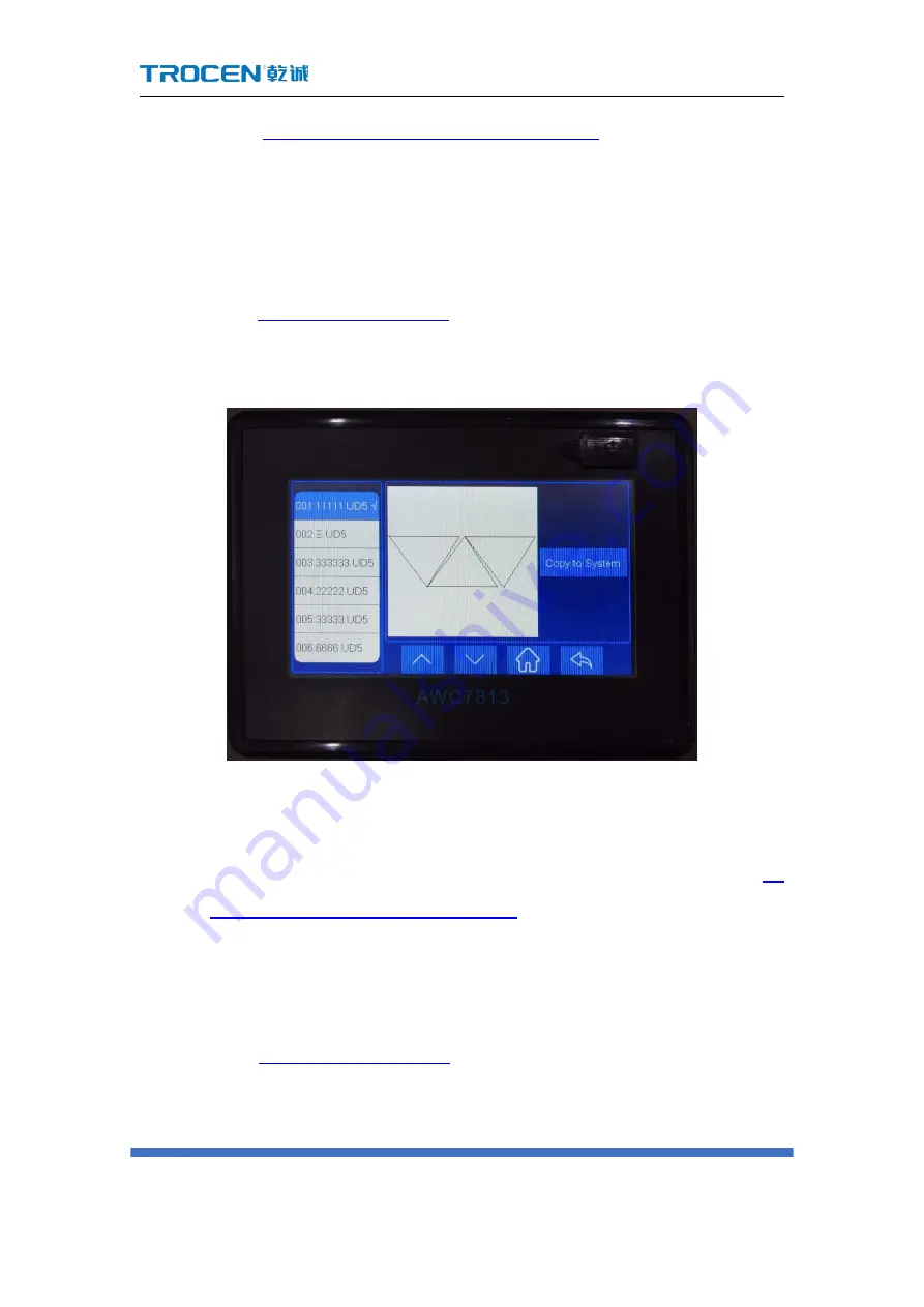
Copy to System

to process the file.

Figure3-12-1 Copy U disk files to the system

3.12.2 Upgrade the mainboard

1) Choose a USB flash drive that meets the requirements, please refer to

4.1

what kind of U disk can the system read?

;

2) Download the latest upgrade file of the corresponding model on the

company's official website;

3) Unzip the upgrade file and copy it to the root directory of the U disk;
4) In the

Figure3-1-2 Main interface 2

interface, click

Menu

】→【

UDisk Files

→【

Upgrade

Files

】→【

Update System

, the system will be automatically

upgraded. After the upgrade, the system will automatically reset. Be careful

Summary of Contents for AWC78 Series

Page 1: ...WWW SZTROCEN COM 1 AWC7813 motion controller User manual Laser motion controller series RV1 3 2020 08 www sztrocen com www awc608 com 2016 Trocen All Rights Reserved ...

Page 2: ...directly or indirectly reproduce manufacture process or use the product and relevant parts thereof Machines in motion are dangerous It is the responsibility of the user to design effective error handling and security protection mechanisms during the use of the machine Trocen shall have no obligation or responsibility for any incidental or consequential damages caused thereby Contact us Shenzhen Tr...

Page 3: ...ases etc You can also call 0755 27958262 for more information about the company and its products Technical support and after sales service You can obtain our technical support and after sales service through the following ways Email qiancheng sztrocen com The phone number 0755 27958262 Sent a letter to 1st Floor Building 4 Zhiheng Strategic Industrial Park Nantou Pass Nanshan District Shenzhen cit...

Page 4: ...ormity assessment procedure and the manufacturer s conformity declaration and complies with the relevant EU directives ROHS certification statement The product has been certified safe by European Union legislation the Directive on Restriction of Certain Hazardous Substances in Electronic And electrical Equipment which conforms to the relevant European Union environmental regulations FCC certificat...

Page 5: ... 2 Hardware interface introduction 11 2 1 Control system electrical wiring diagram 11 2 2 Wiring board unit port description and wiring diagram 11 2 2 1 Power port 11 2 2 2 Universal input port 12 2 2 3 Universal output port 13 2 2 4 Laser power control port 14 2 2 5 Motor driver control port 15 2 2 6 Limit signal input port 16 2 3 Mainboard interface description 18 2 3 1 U Disk interface 18 2 3 2...

Page 6: ... 3 3 2 Fast and slow movement switch key 30 3 3 3 Z axis Movement Button 30 3 4 Processing time display area 31 3 5 Status display area 31 3 5 1 Lock screen unlock screen 31 3 6 Coordinate display area 32 3 6 1 The coordinate system with the machine zero in the upper left corner32 3 6 2 The coordinate system with the machine zero in the upper right corner 33 3 6 3 The coordinate system with the ma...

Page 7: ...a 40 3 10 1 Modify Laser power 40 3 10 2 Modify the power of the file being processed 41 3 11 File operations 43 3 12 U disk transfer files and mainboard upgrade 44 3 12 1 Use U disk to transfer files to mainboard 44 3 12 2 Upgrade the mainboard 45 3 13 Origin Manage 46 3 13 1 Set origin coordinates 47 3 13 2 Move the laser head to the set origin 47 3 14 Motion Parameters Settings 47 3 14 1 Descri...

Page 8: ...s 54 3 15 2 1 AutoFocus Distance mm 55 3 15 2 2 KeyMove Speed mm s 55 3 15 2 3 RunBox Speed mm s 55 3 15 2 4 CutBox Speed mm s 56 3 15 2 5 Blow Open Delay s 56 3 15 2 6 Blow Close Delay s 56 3 15 3 Axis Speed Parameters 56 3 15 3 1 Z Work Speed mm s 57 3 15 3 2 XY Home Speed mm s 57 3 15 3 3 Z Home Speed mm s 57 3 15 4 Rotate Engraving Cutting 58 3 16 Manufacturer Parameters Settings 61 3 16 1 Axi...

Page 9: ...quency hz 69 3 16 2 4 Max Power 69 3 16 2 5 RF Min Power 69 3 16 2 6 Laser 1 Water Protect 69 3 16 3 IO Parameters 70 3 16 3 1 Foot Switch 70 3 16 3 2 Open Protection 71 3 16 3 3 Input Valid Level 71 3 16 4 AutoReset Settings 72 3 16 5 HardLimit Settings 73 3 16 6 Function Configuration 74 3 16 6 1 Z Axis For Autofocus 75 3 16 6 2 Y Z Double Driver Control 75 3 17 Network Settings 76 3 18 Language...

Page 10: ...pt Beyond border limit Continue appear 89 4 4 Why does the prompt Beyond border limit appear 92 4 5 Why does the prompt Trigger limit appear 93 4 6 Why does the prompt No file appear 94 4 7 Why does the prompt To select the file appear 95 4 8 Why does the prompt Continue to work appear 95 4 9 Why does the button movement speed slow down after turning on the rotary engraving function 96 4 10 Why do...

Page 11: ... controller user manual WWW SZTROCEN COM 1 Features AWC78XX Series comparison Terms abbreviations AWC7813 accessories composition Appearance and size of panel Appearance and size of wiring board 1 Product description ...

Page 12: ...ntroller has the following features 5 inch TFT LCD touch screen intuitive and simple operation interface One road laser control Three roads motion axis control X axis Y axis Z axis Using high speed DSP main control chip fast calculation speed advanced motion algorithm All optocouplers isolate external electromagnetic interference and the system works stably and reliably Support Udisk network and U...

Page 13: ...M Data transmission method Network communication USB communication U disk Support laser Various DC lasers RF lasers CO2 lasers Function Input test interface Yes Yes Yes Output test interface Yes Yes Yes Button speed and slow movement function Yes Yes Yes Single axis quick reset operation Yes Yes Yes Quickly return to the positioning point Yes Yes Yes Modify power and speed online Yes Yes Yes Modif...

Page 14: ... function Yes Yes Yes Mainboard online upgrade Yes Yes Yes Automatic feeding Y U synchronous feeding No Yes Yes Over format cutting No Yes Yes Drum cutting function No Yes Yes Blow by layer Yes Yes Yes 1 3 Term abbreviation Table1 3 Explanation of terms and abbreviations Term abbreviation explain PC software LaserCAD software is dedicated software for Trocen laser motion controller TFT LCD panel L...

Page 15: ...ver System hardware The physical objects visible to the system including panel wiring board wires etc 1 4 AWC7813 accessories composition After receiving the product please confirm whether the product and accessories are complete If there is any missing please contact Shenzhen Trocen Automation Technology Co Ltd after sales customer service 1 4 1 AWC7813 all accessories and connection diagram ...

Page 16: ...AWC7813 motion controller user manual WWW SZTROCEN COM 6 1 4 2 List of accessories Table1 4 2 Product list Name Appearance Description panel 1 piece AWC7813 Control panel ...

Page 17: ...te USB cable 1 piece 3m used by the computer to load files to the panel cable 1 piece 5m used by the computer to load files to the panel CN Cable 1piece 1 6m Connect the CN1 port of the panel and wiring board USB extension cable 1piece 0 5m Network extension cord 1piece 0 5m Screw 2pcs Used to fix the panel ...

Page 18: ... user manual WWW SZTROCEN COM 8 1 5 Appearance and size of panel Figure1 5 1 Panel appearance display Figure1 5 2 Panel size diagram 142mm 30mm 3mm 154mm 113mm 113mm C 93mm 142mm CN1 154mm 5 inch touch screen U Disk Jack 154mm ...

Page 19: ...C7813 motion controller user manual WWW SZTROCEN COM 9 209mm 125mm 135mm 1 6 Appearance and size of wiring board Figure1 6 1 Appearance display of wiring board Figure1 6 2 Wiring board size diagram 195mm ...

Page 20: ...motion controller user manual WWW SZTROCEN COM 10 Control system electrical wiring diagram Wiring board unit port description and wiring diagram Mainboard interface description 2 Hardware interface introduction ...

Page 21: ... 2 Wiring board unit port description and wiring diagram 2 2 1 Power port It is used to supply power to the wiring board and the panel When connecting be careful to the positive and negative poles Generally need DC24V3A switching power supply Terminal number Terminal name Description 1 24V 24V power supply positive 2 GND 24V power ground ...

Page 22: ...ilk screen Description 6P terminals 24V 24V power supply positive output IN4 Reserved input signal IN3 Reserved input signal IN2 Foot switch signal IN1 Open protection signal GND Power ground output signal 4P terminals 24V 24V power supply positive output IN6 Reserved input signal IN5 Reserved input signal External earth output signal The signal input electrical wiring diagram is as follows For re...

Page 23: ...hey can be connected to other loads Terminal group Silk screen Description 5P terminals GND Power ground output signal OUT1 Work blowing signal blowing in the whole process of work OUT2 Light blowing signal blowing when lighting OUT3 Paintbrush signal OUT4 Reserved output signal 5P terminals GND Power ground output signal OUT5 Reserved output signal OUT6 Layer blowing signal OUT7 Reserved output s...

Page 24: ...ignal PWM1 Laser power TTL1 Laser switch signal GND Power ground output signal The wiring diagram of the laser power control port is as follows Note When the laser is a radio frequency tube there is no need to connect to the TTL port just connect to the PWM port to control the laser switch and power when the laser is a CO2 glass tube you need to connect the TTL and PWM ports at the same time which...

Page 25: ...or drives Terminal group Silk screen Description X Y Z 5V 5V power positive output connected to the common anode of the driver PUL Pulse signal DIR Direction signal The wiring diagram is as follows Note When the Y Z double driver control is turned on the Z axis direction signal line should be connected to the Y axis direction signal port so that the Y Z ...

Page 26: ...ription 6P terminals GND Power ground output signal X X axis origin limit the input signal of the limit sensor at the minimum coordinate Y Y axis origin limit the input signal of the limit sensor at the minimum coordinate X X axis hard limit the input signal of the limit sensor at the maximum coordinate X limit port generally does not need wiring just setting the format For related content see 3 1...

Page 27: ...imit switch the voltage of the limit signal input port is 24V After the limit switch is touched the voltage of the limit signal input port becomes 0V and limit switch valid level is low level When the selected limit switch is a normally closed switch the voltage of the limit signal input port is 0V After the limit switch is touched the voltage of the limit signal input port is 24V and limit switch...

Page 28: ...e mainboard via U disk For related content see 3 12 U disk transfer files and mainboard upgrade Figure2 3 1 U Disk interface 2 3 2 USB interface The USB interface is the interface that the mainboard and PC access through the USB cable The USB cable and USB extension cable for details please refer to 1 4 2 List of accessories Figure 2 3 2 1 USB interface front view USB cable ...

Page 29: ...e side view 2 3 3 Ethernet interface Through this interface the Ethernet communication between the mainboard and the PC can be realized For details of network cable and network extension cable see 1 4 2 List of accessories Figure 2 3 3 1 Ethernet interface front view Connect to PC cable ...

Page 30: ...TROCEN COM 20 Figure 2 3 3 2 Ethernet interface side view 2 3 4 Panel and terminal board interface Connect the CN1 port of the mainboard and the wiring board through the CN line Figure 2 3 4 Connection port of panel and wiring board Connect to PC ...

Page 31: ... display area Count display area Speed display area Power display area File operations U disk transfer files and mainboard upgrade Origin manage Motion parameters settings Common Parameters Settings Manufacturer parameters settings Network settings Language System Version Input test Output test Cut Box Axis reset Key moving Z autofocus X Y to origin and continue to Previous Work 3 Human Machine In...

Page 32: ...AWC7813 motion controller user manual WWW SZTROCEN COM 22 3 Human Machine Interface Introduction 3 1 Main Interface Preview Figure3 1 1 Main interface 1 Figure3 1 2 Main interface 2 ...

Page 33: ...lize a specific operation function It has the characteristics of simple and clear function orientation and simple and intuitive operation 3 2 1 Reset Figure3 2 1 Reset Graphic display area Processing time display area Coordinate display area Processing file name display area Counting area Speed area Power area Direction key area Function key area Status display area ...

Page 34: ... you may not return to the zero position or mistakenly believe that the non zero position is the zero point and the cutting or engraving graphics will exceed the Range mm Please refer to the definition of Range mm 3 16 1 6 Range mm No matter what state the system is in press this key to return to the standby state and restart operation 3 2 2 File Figure3 2 2 File In the Figure3 1 2 Main interface ...

Page 35: ...mmon parameters Settings Manufacturer Parameters Settings Network Settings Language System Version eight functions For details please refer to 3 12 3 19 3 2 4 More Figure3 2 4 More In the Figure3 1 2 Main interface 2 click the More button Can enter Ins Outs Cut Box Reset Move Other interface For details please refer to 3 20 3 25 3 2 5 Laser Figure3 2 5 Laser In the Figure3 1 1 Main interface 1 pre...

Page 36: ...RunBox Speed For the definition of RunBox Speed please refer to 3 15 2 3 RunBox Speed and it is a rectangular graph This button is to test the size of the processed graphics and the currently selected positioning point that is you can view the approximate position and range of the graphics on the material by walking the box 3 2 7 Origin Figure3 2 7 origin In the Figure3 1 1 Main interface 1 click ...

Page 37: ...in Mode 3 2 8 Stop Figure3 2 8 Stop This icon will only be displayed when the machine is working When the machine stops this icon will automatically switch to Box icon In the Figure3 1 1 Main interface 1 click the Stop button to stop the running machine back to position point If you want to continue processing after stopped file can click Continue to Previous Work For details please refer to3 25 3...

Page 38: ... be used Press this key to set the speed and power of the file being processed For details please refer to3 9 2 Modify the speed of the file being processed 3 10 2 Modify the power of the file being processed 3 2 11 Interface switching Figure3 2 11 Interface switching icon In the main interface press this key to switch Figure3 1 1 Main interface 1 and Figure3 1 2 Main interface 2 3 3 Direction key...

Page 39: ...ss X Y axis movement key to move X Y axis 1 Y axis up move key control Y axis to move up Figure3 3 1 1 Y axis up key 2 Y axis down key control the Y axis to move down Figure3 3 1 2 Y axis down key 3 X axis left key control the X axis to move left Figure3 3 1 3 X axis left move key 4 X axis right key control the X axis to move right Figue3 3 1 4 X axis right move key ...

Page 40: ... X Y axis the slow moving speed defaults to the start speed in the motion parameters the default fast moving speed is KeyMove Speed When moving the Z axis the slow moving speed defaults to the jumping speed in the Z axis parameters the fast moving speed is KeyMove Speed For details please refer to 3 14 1 6 Start Speed 3 15 2 2 KeyMove Speed Figure3 3 2 1 Slow movement Figure3 3 2 2 Fast moving 3 3...

Page 41: ...the status display area shows the proportion of the current file completed when not working it shows as idle when the current work is paused it shows as pause For details please refer to Figure3 1 3 Main interface area division 3 5 1 Lock screen unlock screen To prevent misoperation the screen can be locked if necessary In the Figure3 1 3 Main interface area division interface click anywhere in th...

Page 42: ...rent and the coordinate system is also different There are four coordinate systems with the machine zero at the upper left corner upper right corner lower left corner and lower right corner According to different coordinate systems to determine whether the graph is beyond the interface For details please refer to 4 3 Why does the prompt Beyond border limit Continue appear 3 6 1 The coordinate syst...

Page 43: ...machine zero the machine limit position is in the upper right corner the X axis coordinate increases when the laser head moves to the left and the Y axis coordinate increases when the laser head moves down as shown in the following figure 3 6 3 The coordinate system with the machine zero in the lower left corner When the machine zero the machine limit position is at the lower left corner the X axi...

Page 44: ...shown in the following figure 3 6 4 The coordinate system with the machine zero in the lower right corner When the machine zero the machine limit position is in the lower right corner the X axis coordinate increases when the laser head moves to the left and the Y axis coordinate increases when the laser head moves up as shown in the following figure 0 0 ...

Page 45: ...he graphics size of the current processing file through X size mm and Y size mm Figure3 7 1 Property graph Table3 7 1 Description of property interface Name Function Description Repeat Count The number of repeated processing files If the Repeat Count is set to 2 the file will be processed twice Repeat delay s The waiting time from the end of file processing to the next repeated processing of the f...

Page 46: ...size of the graphic Combining the two with the coordinates of the anchor point can determine whether the graphic is beyond the interface For details please refer to 4 3 Why does the prompt Beyond border limit Continue appear 3 7 2 Layer parameters of processing files In the Figure3 1 3 Main interface area division interface click the numeric key after File name Layer1 Speed Power1 to modify the sp...

Page 47: ...e maximum power and the latter is the minimum power When the file is being processed the power area of the main interface displays the power of the processing file The maximum power of the processing file cannot exceed the MaxPower in Laser Parameters for related content please refer to 3 16 2 4 Max power Speed and power jointly determine the depth of the cutting file and whether it can be cut thr...

Page 48: ...WC7813 motion controller user manual WWW SZTROCEN COM 38 Light Single of Array For details please refer to 3 15 1 4 Count Mode Figure3 8 1 To Clear Current Counts Figure 3 8 2 To Clear Cumulative Counts ...

Page 49: ...in Common Parameters will also change accordingly For details please refer to 3 15 2 2 KeyMove Speed Figure3 9 1 Quickly modify the key move speed 3 9 2 Modify the speed of the file being processed When the machine is working the speed area displays the working speed of the laser head in Figure3 1 3 Main interface area division interface that is the speed of processing files After clicking the Pau...

Page 50: ...ocessed 3 10 Power display area 3 10 1 Modify Laser power When the machine is idle the power area displays the laser power in Figure3 1 3 Main interface area division interface the former is the maximum power and the latter is the minimum power At this time you can click the numeric key after Power to modify ...

Page 51: ...fy the mini laser power 3 10 2 Modify the power of the file being processed When the machine is working the power area displays the working power of the laser head in Figure3 1 3 Main interface area division interface that is the power of the processing file After clicking the Pause button this value can be modified The ...

Page 52: ...d value is only valid in the current job and it will be restored to the value before modification when the work of this file is completed Figure3 10 2 1 Modify the max power of the file being processed Figure3 10 2 2 Modify the mini power of the file being processed ...

Page 53: ...ration interface Browse the file name on the left and click on the Select Data Check Copy Delete All Delete button on the right Figure3 11 File operation Table3 11 Description of file operation functions Name Function Description Select Click the file sequence name on the left and then click Select to select the file and the screen immediately jumps to the main interface The file displayed on the ...

Page 54: ...k Copy to U Disk and the file will be copied to the U disk Delete Click Delete and the selected file will be deleted All Delete Click All Delete all files in the mainboard will be deleted 3 12 U disk transfer files and mainboard upgrade Please refer to the USB flash drive interface content 2 3 1 U Disk interface Figure3 12 U disk transfer files and mainboard upgrade 3 12 1 Use U disk to transfer f...

Page 55: ...UDisk Files Work Files Copy to System to process the file Figure3 12 1 Copy U disk files to the system 3 12 2 Upgrade the mainboard 1 Choose a USB flash drive that meets the requirements please refer to 4 1 what kind of U disk can the system read 2 Download the latest upgrade file of the corresponding model on the company s official website 3 Unzip the upgrade file and copy it to the root director...

Page 56: ...f or reset during the upgrade process The upgrade will be completed within 20 seconds Figure3 12 2 Upgrade the mainboard 3 13 Origin Manage The origin coordinates are mainly used to accurately and quickly switch between different laser head positions Figure3 13 Origin manage ...

Page 57: ...in to set it and the other three origin are the same 3 13 2 Move the laser head to the set origin When the laser head position is not at the required origin in the Figure3 1 2 Main interface 2 interface click Menu origin manage origin 1 Move head to the origin to set it 3 14 Motion Parameters Settings Motion parameters are restricted by Axis Parameters in Manufacturer Parameters Settings If the us...

Page 58: ...e Ranges Depending on the machine s endurance speed the value increases or decreases in units of 50 The maximum value is the smaller value of Max Speed of X and Y axis parameters For example the Max Speed in X Axis Parameters is 500 and the Max Speed in Y Axis Parameters is 600 At this time the maximum value of Space Speed is 500 Space Speed cannot be set too small otherwise the efficiency of proc...

Page 59: ...not emit light the amount of change in acceleration during movement the greater Space Jerk the faster the idling speed of the machine At the same time it may cause Jitter occurs when a machine finishes cutting a graph and starts cutting the next graph The unit is mm s3 2 Value Ranges The value range is 1 20 and the default value is 10 The value increases or decreases in units of 1 3 14 1 4 Min Acc...

Page 60: ...ection the Engrave Acc cannot exceed the Max Acc of X Axis Parameters please refer to 3 16 1 8 Max Acc Engrave Acc can not be set too small otherwise the distance of the laser head space move on the outside will be too long which will easily lead to overstepping during engraving 3 14 1 6 Start Speed 1 Definition The initial speed of laser head from rest to motion the unit is mm s 2 Value Ranges Th...

Page 61: ...default value is 3 The larger the Speed Factor the faster the curve cutting speed 3 14 2 Example analysis 3 14 2 1 Wavy lines appear when cutting arcs When cutting small circles and small arcs the arcs at the corners of non circular shapes the laser head jitters resulting in poor cutting results This is because Speed Factor is too large If the Speed Factor is reduced the small circles and arcs to ...

Page 62: ...the corners resulting in poor cutting results This is because the Min Acc or Cut Jerk is set too large and you need to reduce the Min Acc or Cut Jerk at this time Solution First adjust the Min Acc to the minimum value of 100 If the Wavy lines does not appear at this time there is no need to adjust the Cut Jerk if the wavy lines still appears reduce the Cut Jerk 3 15 Common Parameters Settings 3 15...

Page 63: ...Origin Mode Origin Please refer to 3 2 7 Origin Current Position Set the current position of the laser head as the origin wherever the laser head stops it will be the origin no key operation required Key Origin After selecting Origin return to the main interface move the laser head to the chosen position and click Origin Soft Origin set the origin point when drawing a graph on LaserCAD software Ma...

Page 64: ...t since all finished 3 15 1 4 Count Mode Count per work Count plus one after processing all graphics in one format Count per Light When the laser head emits light it counts plus one Single of Array The count of a solid line figure in the array is increased by one after processing 3 15 2 Common Parameters In the Figure3 1 2 Main interface 2 interface click Menu Common Parameters Settings Common Par...

Page 65: ...peed mm s is modified in Common parameters interface the key movement speed of the main interface will change accordingly KeyMove Speed mm s refers to the axis movement speed when pressing the arrow key on the panel The maximum value of KeyMove Speed mm s cannot exceed the smaller value of Max Speed of X and Y axis parameters If the Max Speed of the X axis is 500 and the Max Speed of the Y axis is...

Page 66: ...related content please refer to 3 22 Cut Box 3 15 2 5 Blow Open Delay s The time interval from when the machine starts to blow air until the laser head emits light Setting too large will affect the cutting efficiency and it will pause for a while before cutting 3 15 2 6 Blow Close Delay s The time interval from when the laser stop to when the blowing stops Setting too large will affect the cutting...

Page 67: ...arameters The unit is mm s For details please refer to 3 16 1 9 Max Speed 3 15 3 2 XY Home Speed mm s The reset speed of XY axis The maximum value of XY Home Speed mm s cannot exceed 200 The unit is mm s 3 15 3 3 Z Home Speed mm s The reset speed of Z axis the maximum speed cannot exceed 200 Z Axis for Autofocus on the reset speed For the definition of Z Axis for Autofocus please refer to 3 25 1 R...

Page 68: ...g Cutting is turned on set Pulse Count Per Rotate and Current Diameter mm Distance Per Pulse Circumference Length Pulse Count Per Rotate the pulse equivalent value will change at this time so when the direction key is pressed the axis movement becomes slower Rotary Axis The axis which rotary engraving uses Pulse Count Per Rotate The pulse counts for the motor to make the rotary axis rotate one cir...

Page 69: ... is Enabled If the current machine does not support the rotate engraving function the distance per pulse of rotary axis will change and the machine cannot cut the graphics normally After turning off the function reset the machine again users do not need to set axis parameters like distance per pulse the machine can work normally Note For machines that do not support the Rotate Engraving Cutting fu...

Page 70: ... Engraving Cutting no need to turn on Rotate Engraving Cutting and directly adjust Rotary Axis Distance Per Pulse um Pulse Count Per Rotate is invalid Take the X axis as the rotation axis as an example i Wrap a layer of paper around the roller ii In the computer software LaserCAD draw a straight line section with fixed length as A less than the current cutting object girth iii Click Start key to c...

Page 71: ... into Expected Length option fill B into the Actual Length option and click Enter key to calculate the distance per pulse of X axis rotary axis Figure 3 15 4 4 Roller Rotate Engraving Cutting 3 16 Manufacturer Parameters Settings 3 16 1 Axis Parameters take X axis as an example In Figure3 1 2 Main interface 2 interface click Menu Manufacturer Parameters Setting Axis Parameters X Axis Parameters to...

Page 72: ...l the machine is easy to jam and the response is slow if the Distance Per Pulse is set too large it will cause insufficient cutting accuracy The unit is um The steps to modify Distance Per Pulse are as follows 1 In Figure3 1 2 Main interface 2 interface click Menu Manufacturer Parameters Settings Axis Parameters X Axis Parameters Distance Per Pulse 2 Click the Axis Move button on the upper right t...

Page 73: ...ser head to a certain position click the laser button then close the axis movement screen and then click the Step 2 Set As End Position button and set this as point B Figure3 16 1 1 2 Set end point 4 Measure the actual distance between points AB with a measuring scale and click the value after Step 3 Input the Measured Distance mm enter the ...

Page 74: ...et As End Position is the same as the actual measurement no need to modify Distance Per Pulse Figure3 16 1 1 3 Measured distance 5 Click the Step 4 Change the Pulse Value button click to set the Distance Per Pulse Figure3 16 1 1 4 Modify distance per pulse 6 Distance Per Pulse needs to check whether it is correct after setting ...

Page 75: ...eturning to the positioning point at the end of each repeated cutting it will shift in one direction and when cutting a large figure the figure will shift in one direction 3 16 1 3 Datum Direction Datum Direction refers to the direction in which the motion axis moves when the machine is reset When the setting is wrong the axis will reset in the opposite direction When you click the Reset button or...

Page 76: ...will receive a signal of 1 If the panel is set to High Level at this time the machine will stop if it does not touch the limit switch when it is running The limit sensor is of NPN type and the Limit Switch Valid Level is set to Low Level the limit sensor is of PNP type and the Limit Switch Valid Level is set to High Level For related wiring content see 2 2 6 Limit signal input port 3 16 1 6 Range ...

Page 77: ...0 and the Max Acc of the Y axis is 600 So Max Acc is 500 This value limits the maximum value of Engrave Acc in Motion Parameters For details please see 3 14 1 5 Engrave Acc 3 16 1 9 Max Speed Max Speed refers to the highest limit speed that the motion axis can bear The maximum value of Max Speed Distance per pulse 180 when it exceeds this value it will default to distance per pulse 180 This value ...

Page 78: ...e3 16 2 Laser parameters setting 3 16 2 1 Laser Mode As for laser mode CO2 glass tube and radio frequency tube are optional Please refer to the wiring differences between the two lasers 2 2 4 Laser power control port 3 16 2 2 TTL Valid Level TTL Valid level refers to the control level of the laser tube which can be set to low level the TTL pin of the wiring board is connected to the L pin of the l...

Page 79: ...0 3 16 2 4 Max Power Max power refers to the limit power of the laser tube The laser power and the power of the processing file cannot be higher than the maximum power The laser power is displayed as a percentage generally set to 98 to prevent damage to the machine due to excessive power For the laser power and processing file power please refer to 3 10 1 Modify Laser power Table3 7 2 description ...

Page 80: ...ng to protect the laser tube 3 16 3 IO Parameters In Figure3 1 2 Main interface 2 interface click Menu Manufacturer Parameters Settings IO parameters to enter the corresponding interface Figure3 16 3 IO Parameters 3 16 3 1 Foot Switch Use the foot pedal to control the operation of the machine step on the machine to start running and then step on the machine to stop running and enable this function...

Page 81: ...nnected to work is the same as the corresponding input IO effective level configuration in the panel otherwise the Opened Protected prompt will appear The modification steps are as follows 1 Connect the corresponding hardware the signal pin of the mainboard corresponding to the open protection is IN1 please refer to the relevant wiring content 2 2 2 Universal input port 2 Ensure that the effective...

Page 82: ...acturer Parameters Settings AutoReset Settings to turn it on Figure3 16 4 Autoreset settings Table 3 16 4 Power on reset setting instructions Name Function Description XY AutoReset Generally it is on The process of power on reset is actually the process of finding the zero point The X and Y axes drive the laser head to move in the X and Y directions stop when it touches the X and Y limit switches ...

Page 83: ...on it needs to be turned on After it is turned on the Z axis drives the laser head to move down and stops when it hits the Z limit switch 3 16 5 HardLimit Settings Please refer to the description and wiring of the limit signal input port 2 2 6 Limit signal input port Generally setting the format size can control the operating range of the laser head If you need to turn on the hardware limit the st...

Page 84: ...prevent the laser head from hitting the edge and going beyond the interface If this function is turned on the laser head will stop operating when it touches the limit switch and prompts Trigger limit Y HardLimit Same as above Z HardLimit Same as above 3 16 6 Function Configuration In Figure3 1 2 Main interface 2 interface click Menu Manufacturer Parameters Settings Function Configuration to enter ...

Page 85: ... Y Z Double Driver Control is activated the AWC7813 control board drives two motors to control the movement of the laser head on the Y axis When resetting the machine will touch the two limit switches Y and Z the order of which depends on the tilt angle of the cross beam If you tilt to the Y limit switch the machine will first touch the Y limit switch and then touch the Z limit switch and vice ver...

Page 86: ...re two situations Direct connection between AWC7813 control panel and computer 1 Set the software IP address select network communication in the software Figure 3 17 1 Set software IP address 2 Set the computer network card IP address Figure3 17 2 Set the computer network card IP address ...

Page 87: ...nsmitted by the switch as the transfer station 1 Click on the lower right corner of the computer to determine the IP address of the computer by viewing the network status 2 Set the software IP address The first three digits are the same as the computer and the last digit is different from the computer The software selects network communication 3 Set the control card IP address to be consistent wit...

Page 88: ...tion controller user manual WWW SZTROCEN COM 78 click Load to send the data 3 18 Language Figure3 18 language selection In Figure3 1 2 Main interface 2 interface click Menu Language to select 3 19 System Version ...

Page 89: ...age 1 In Figure3 1 2 Main interface 2 interface click Menu Page Turning Key System Version to learn about this system version 2 Check Version if the version is relatively old you can download the latest version upgrade from our company website 3 20 Input Test Figure3 20 Input test ...

Page 90: ...no change it may be that the input port is broken The specific change is from 1 to 0 or from 0 to 1 For related wiring content see 2 2 2 Universal input port 3 21 Output Test Figure 3 21 Output test Mainly test whether all output signals are normal 1 In Figure3 1 2 Main interface 2 interface click More Outs 2 When the peripheral is not connected normally the idle state of the system is 0V and it i...

Page 91: ...e processed and the cut is a rectangular graph In Figure3 1 2 Main interface 2 interface click More Cut Box Blank Distance Start cutting box to operate Note If you cannot cut through you can increase the laser power or decrease the speed of the frame Figure3 22 1 Cut Box Table3 22 Cut border parameter description Name Function Description blank distance The distance between the position of the gra...

Page 92: ...nd cut box Same Both follow the same path Difference The former laser head does not emit light while the latter laser head emits light The main purpose of walking the frame is to test the position and size of the graphic on the material and the purpose of cutting the frame is to cut off the outer frame of the graphic 3 23 Axis Reset During debugging a certain axis can be reset separately to make t...

Page 93: ...gure3 23 Axis reset 3 24 Key Moving Figure3 24 Key moving 1 In Figure3 1 2 Main interface 2 interface click More Move Jog distance the selection box in front when it becomes you can jog control 2 Move the direction axis the set value can be accurately moved once ...

Page 94: ...Previous Work Figure3 25 Z Autofocus X Y to origin and continue to previous work 3 25 1 Run Z AutoFocus function In Figure3 1 2 Main interface 2 interface click More Others Z AutoFocus to automatically complete focusing During Z axis auto focusing the Z axis drive workbench moves down at Z axis reset speed Z Home Speed please refer to3 15 3 3 Z Home Speed mm s stop after touching the Z limit switc...

Page 95: ...nction is turned on set the AutoFocus distance and then click this button to start auto focus For details see 3 15 2 1 AutoFocus Distance mm 3 16 6 1 Z Axis For AutoFocus Only after the Z axis for autofocus function is turned on the Z AutoFocus function in the Other interface is valid when it is turned off the function is invalid and turns gray As shown below Figure3 25 1 Z axis auto focus is inva...

Page 96: ...at the file position where you stopped last time which can avoid the problem that you want to continue processing due to sudden power failure or interruption of the last file being processed When the file has been processed the Continue to previous work function is invalid and the Continue to previous work button becomes gray as shown in the figure below Figure3 25 3 continue to previous work is i...

Page 97: ...mpt Beyond border limit prompt appear Why does the prompt Trigger limit appear Why does the prompt No file appear Why does the prompt To select the file appear Why does the prompt Continue to work appears Why does the button movement speed becomes slow after turning on the rotary engraving function Why does the prompt water protect prompt appear Why does the prompt opened protected prompt appear 4...

Page 98: ...disk 1 U disk must be formatted as FAT32 file system in advance please do not select quick format when formatting U disk other file formats cannot be read 2 Due to the different quality of the USB flash drives some USB flash drives may not be able to read please try to use a regular USB flash drive when the USB flash drive is still unable to read please replace other USB flash drives 3 U disk memo...

Page 99: ...nt is set too far it will easily cause the laser head to go beyond the boundary during idling on the outside Once the boundary is exceeded it will prompt Engrave beyond the border limit and the machine will stop operating At this time you need to adjust the positioning point in time taking into account the distance that the laser head travels outside Please refer to the definition of anchor point ...

Page 100: ...rder limit Continue Therefore when setting the anchor point you can combine X size with Y size and the position of the small blue dot to estimate whether the graphics are out of bounds When the positioning key is pressed the X and Y coordinates of the coordinate area display the coordinates of the positioning point see Figure4 3 3 Graphic size and anchor point coordinates Take the machine origin a...

Page 101: ...e3 7 1 Property graph see the format 3 16 1 6 Range mm coordinate system please see 3 6 coordinate display area At the same time you must refer to the small blue dot on the display screen when setting the anchor point and not too biased You can walk the border advanced to check whether the position of the anchor point and the size of the processed graphics are out of bounds Please refer to the bor...

Page 102: ...ue Figure4 3 3 Graphic size and anchor point coordinates 4 4 Why does the prompt Beyond border limit appear When the positioning point is too deviated and the size of the processed graphics exceeds the format press the Box key at this time and the prompt will Anchor point coordinates X size Y size ...

Page 103: ...er head touches the limit switch during operation the prompt Motion axis has touched the limit switch will appear and the machine will stop operating Or the Limit switch valid level setting is wrong press the direction key to move the machine and the Trigger limit prompt appears when the machine does not reach the limit switch position and the machine stops operating Limit switch valid level can b...

Page 104: ...does the prompt No file appear When all the files on the mainboard are accidentally deleted click the File button in Figure3 1 2 Main interface 2 interface this prompt will appear At this time files can be transferred to the mainboard via U disk network or USB communication Figure 4 6 No file ...

Page 105: ...e this prompt will appear At this time files can be transferred to the mainboard via U disk network or USB communication Figure 4 7 To select the file 4 8 Why does the prompt Continue to work appear When the machine suddenly cuts off power while the file is being processed the machine will pop up the prompt Continue to work after it is powered on Click to continue cutting the remaining part and cl...

Page 106: ... function For details see Table3 15 4 Rotate Engraving Cutting Instruction 4 10 Why does the prompt water protect appear When the Laser 1 water protect function is turned on the mainboard detects the WP1 signal during the operation of the machine and it will prompt Water protect then please check the water protection switch For details see 3 16 2 6 Laser 1 Water Protect ...

Page 107: ...and the machine detects the Open Protection signal the machine stops operating and prompts the words Opened Protected It is also possible that when the input valid level is wrong it will also cause the words opened protected to appear At this time please check the related equipment and functions Please refer to the definition and settings of Open Protection 3 16 3 2 Open Protection ...

Page 108: ...AWC7813 motion controller user manual WWW SZTROCEN COM 98 Figure4 11 Opened protected ...

Page 109: ...AWC7813 motion controller user manual WWW SZTROCEN COM 99 5 Operation process description Machine installation and debugging process Basic steps of using a laser machine to cut graphs ...

Page 110: ...t the laser power water protection see details 2 2 4 Laser power control port 4 Turn on the required axis power on reset please refer to 3 16 4 AutoReset Settings 5 Set Limit switch valid level Limit switch valid level default is Low level please refer to 3 16 1 5 Limit Switch Valid Level 6 Set Datum direction please refer to 3 16 1 3 Datum direction 7 Set Key Direction please refer to 3 16 1 4 Ke...

Page 111: ... method and transfer the file to the control card 7 Move the laser head to estimate the approximate position of the cut image and press the Origin key on the panel 8 Press the Box key to check the size and position of the figure and place the material 9 Press the Start key and the machine will start cutting If you find that the cutting effect is not good press the Pause key to adjust the power and...

Page 112: ...enzhen Trocen Automation Technology Co Ltd Without the permission of Trocen no unit or individual shall arbitrarily imitate copy reprint or distribute the relevant content of this manual The contents of this manual are subject to update without notice If you encounter some problems during use or use difficulties please contact us in time Add First Floor Building 4 Zhiheng Industrial Park Nantou Pa...

Reviews: