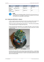
Installation
Intelligent Gyro Compass (iGC)
0707-SOM-00004-7
18
© Tritech International Ltd.
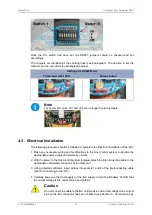
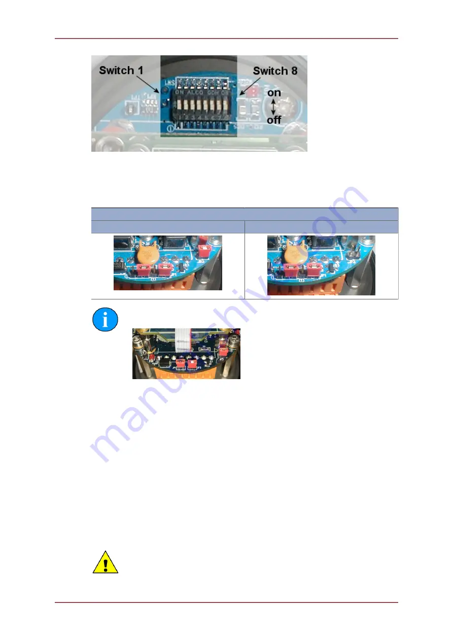
Once the DIL switch has been set, the RS485 jumpers should be checked and set
accordingly.
The Jumpers are identified as the shorting links (see photograph). The position to set the
Jumpers can be seen from the photographs below:
Settings for RS485 Mode
Terminated with 120R
Unterminated
Note
For newer iGC units, JP1 and JP2 are no longer tri-state jumpers.
4.5. Electrical Installation
The following procedure should be followed to complete the Electrical Installation of the iGC:
1. Make any necessary wiring and modifications to the Host control system to provide the
appropriate power supply and telemetry circuits
2. With the power to the Host control system isolated, attach the interconnecting cable to the
appropriate underwater connector at the Host end
3. Using a digital multimeter, insert probes into sockets 1 and 2 of the interconnecting cable
(prior to connecting to the iGC)
4. Carefully power-up the Host supply (or the iGC supply circuit if switchable). Confirm that
the output voltage is the correct value and polarity
Caution
Do not connect the cable to the iGC until provision of correct voltage to the correct
pins on the iGC connector has been checked (see Section 5 - Commissioning).

