Installation
Intelligent Gyro Compass (iGC)
0707-SOM-00004-7
15
© Tritech International Ltd.
4.2.4. Stiffness
The iGC should be rigidly mounted so that flexibility and / or system vibration does not affect
the outputs.
4.2.5. Collision Protection
To protect against accidental damage, the iGC should be mounted in a protected location.
The protection around the iGC should not be manufactured form a ferrous material.
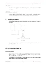
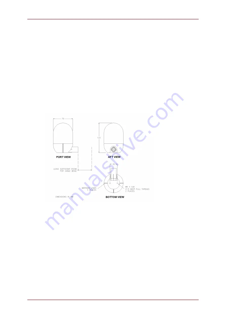
4.3. Installation Drawing
The following drawing shows installation dimensions and fastener details for the installation
of the iGC:
NB: As stated previously non-magnetic fasteners and mounting bracket should be used for
mounting the iGC.
4.4. iGC Electrical Installation
4.4.1. Preparation
All electrical connections to the iGC are via a single Subconn 8-pin micro series connector.
This connector is a Male on the iGC (MCBH8MSS) and therefore a female is required on the
interface cable (MCIL8F or equivalent).
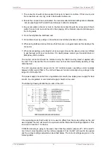
The connector should be made up in accordance with Subconn guidelines, as detailed below
(taken from MacArtney Subconn standard literature):


