6 L'f!t�nfit!
VIDEO TEST MODULE
Instruction Manual
1. Introduction
Triplett's LVPro Video Test Module provides an easy way to extend the test
and diagnostic capabilities of your LVPro20 or LVPro30 cable tester by simply
attaching the expansion connector harness in the LVPro20 or LVPro30 cable
tester to the module, and then securing the module to the tester. No ad
ditional software updates are required. The Video Test Module allows you
to perform HDMI cable testing and type identification with the included Video
Remote unit, generate a VGA resolution test pattern for checking monitor
connections, and perform a basic DOC Channel test with HDMI cables. The
Video Test Module also enables you to perform RF signal level measurement
tests on RG6/RG59 type coaxial cables with either F-Type or BNC termina
tions, as well as to perform dB loss measurements and coaxial cable installa
tion mapping with numbered Video Remotes. These features help to make
you more productive with your LVPro20 or LVPro30 cable tester and maintain
your investment in this multipurpose tool. The Video Test Module is powered
by the LVPro20 or LVPro30 that it is attached to and requires no batteries of
its own. The Video Remote Modules are powered by readily available 3V
coin cell batteries (Panasonic CR2450).
2. Video Test Module Installation
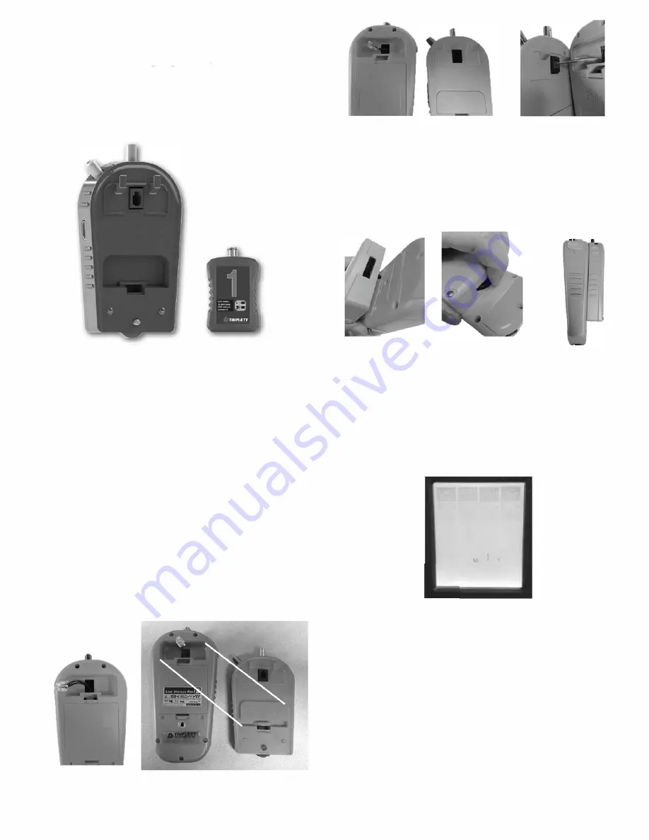
To install the Video Test Module, first power off the LVPro20 or LVPro30 cable
tester and place it face down on a flat surface and remove the access panel
located above the battery compartment on the back of the tester's case. Sim
ply push upward on the plastic tab on the cover labeled "Snap On Adapter"
and lift the cover from the LVPro tester's case.
•
There is a matching space on the Video Test Module case where you can
snap this cover into place for safe keeping while the Video Test Module is
installed on the LVPro.
Hold the Video Test Module so that the RJ 11 connector on its back is near
the snap on adapter cover space on the LVPro and insert the RJ11 harness
plug into the Video Test Module's connector until it clicks into place. Lower
the Video Test Module toward the back of the LVPro so that the two retain
ing hooks on the Test Module's case near the RJ11 connector go into the
two slots in the LVPro's case in the top of the snap on adapter area. The
threaded thumbscrew on the bottom of the Video Test Module should align
with the threaded metal insert near the lower end of the LVPro tester case.
Turn the thumbscrew clockwise to thread it into the insert and securely attach
the Video Test Module case to the LVPro case. Your Video Test Module is
now ready to use!
3. Video Test Menu Access
After the Video Test Module has been securely attached, turn on the LVPro
cable tester. It should power up and display the same startup screen as
before. To access the newly added Video Test Module functions, simply use
the Left Arrow or Right Arrow buttons to navigate through the test category se
lections at the top of the screen. When the right arrow is pressed to navigate
past the DATA RJ45 test category on the right of the screen, or the left arrow
is pressed to navigate past the VOICE RJ11 category on the left side of the
screen, the LVPro will check to see if the Video Test Module is installed. If it
finds one, it will display an "X" on the LCD and show a flashing menu prompt
of the module type and the number of tests available (VIDEO 1-7).
VOICE VIDEO SPKR DATA
RJl 1
COAX ALARM RJ45
0
U ldE" _,
I
f no Video Test Module is found, the LVPro's LCD display will simply scroll
around to the opposite side of the LCD screen and select the next test cat
egory as it normally does.
To enter the Video Test Module menu selection mode, simply press either
the OK button, the Up Arrow button, or the Down Arrow button. The "X" will
continue to be displayed, and the prompt will change to show which test is
selected by displaying the word "VIDEO" and flashing the test number. Press
the Up Arrow or Down Arrow button to change the selected test number to
the desired test. To execute the test corresponding to the flashing number,
simply press the OK button. The Hammer Icon will activate and remain ac
tive while the test is running. To stop a test, simply press the Exit Button to
return to the menu selection mode where you can use the Up Arrow or Down
Arrow keys to select a different test, or press the Exit button again to return
to the top level video module menu (flashing VIDEO 1-7 prompt). From
here, either press the Exit button or the Left Arrow or Right Arrow buttons to
return to the other LVPro cable test categories.
The Test Number chart on the case of the Video Test Module provides a
quick reference to identify the test functions and the Video Test Module port
connector to be used for each video test number selection in the menu.
Test Equipment Depot - 800.517.8431 - 99 Washington Street Melrose, MA 02176 - TestEquipmentDepot.com


