Trinamic TMCM-078 Manual Download Page 20

TMCM-078 Manual (V1.03 / September 10th, 2008)   

20 

Copyright © 2008, TRINAMIC Motion Control GmbH & Co. KG 


5.3.2


Step  


Description:

 The Step signal controls the velocity and acceleration of the motor. The velocity depends 

on the frequency, the acceleration on the change of the frequency. One step impulse represents one 
microstep. 
Calculation of rotations per second: 

]

s

/

rotations

[

resolution

Microstep

Fullsteps

frequency

input

Step

]

s

/

rotations

[

v


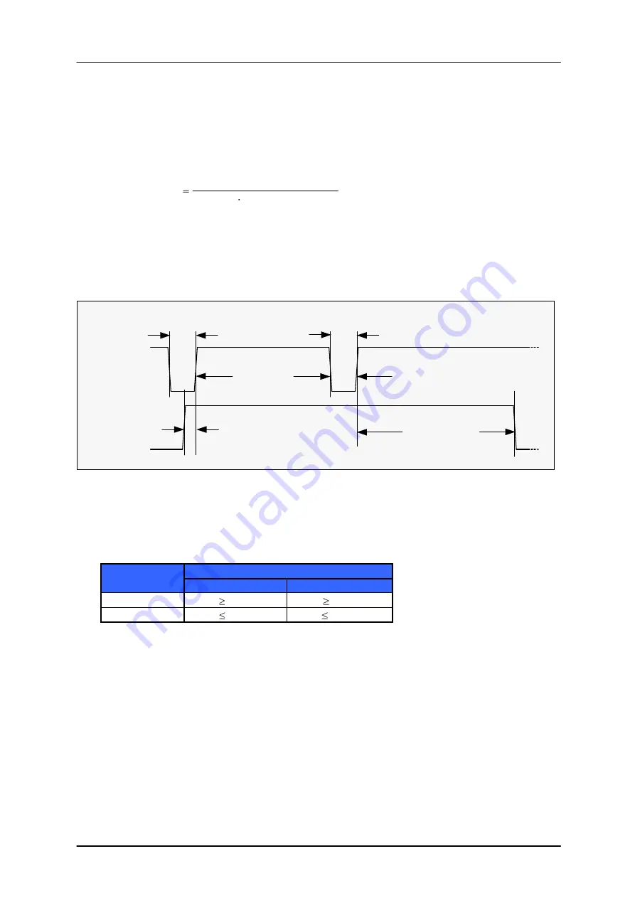
Maximum  frequency  at  screw  connector  (decoupled  by  opto  couplers):

  The  maximum  Step  input 

frequency is 350 kHz, aligned to the Direction signal. It is limited by the switching capabilities of the 
optocouplers. The minimum logic ”0” time is 0.7 µs and the minimum logic “1” time is 2.0 µs. A step 
is triggered by the positive going edge of the signal (switching off of opto coupler). 
Maximum frequency at a duty cycle of 1 (“0” time is 2.0 µs and “1” time is 2.0 µs) is 250 kHz. 
 

step pulse

direction

0.7µs min

2.0µs min

0.7µs min

t

DIRHOLD

t

DIRSETUP


Figure 5.3: Step and Direction Signal (schematically, optocoupler input at screw connector) 


Maximum  frequency  at  JST  connector: 

Even  higher  than  at  screw  connector.  Limited  by 

microcontroller but not yet evaluated (approximately 300 kHz without microstep loss). 
 

Function Table: 

Step signal 

Differential signal 

Screw connector 

JST connector 

high 

 3.5 V 

 0.4 V 

low 

 2.0 V 

 -0.4 V 


5.4


RS485 interface 

The  RS485  interface  can  control  all  functions  of  the  TMCM-078.  It  is  possible  to  change  parameters, 
with this interface which are also valid in the other modes like max. velocity or acceleration. Most of 
the  parameters  that  can  be  change  by  the  RS485  commands  (except  those  that  are  set  by  the  DIP 
switches) can also be stored in the FlashROM of the module. 
The factory default address setting is “A” and the default baud rate is 9600 baud. Use an appropriate 
RS485  interface  (like  Trinamic  USB-2-485)  to  enter  RS485  commands  using  a  terminal  program  (e.g. 
Hyperterminal that is shipped with Windows). 
Many  commands  are  the  same  as  those  used  on  the  TMCM-013  and  IDX  modules,  but  some 
commands are different. Also the parameter ranges of many commands are different from those on 
the TMCM-013 and IDX modules. 
 

Summary of Contents for TMCM-078

Page 1: ...078 Manual 1 axis stepper motor controller driver module 7A RMS 9 8A peak 75V with step direction interface Trinamic Motion Control GmbH Co KG Sternstra e 67 D 20357 Hamburg Germany http www trinamic...

Page 2: ...on 19 5 3 1 Direction 19 5 3 2 Step 20 5 4 RS485 interface 20 5 4 1 RS485 command overview 21 Example for test move 22 5 4 2 Commands A and a Set or read back acceleration 22 5 4 3 Commands C and c Se...

Page 3: ...re 5 3 Step and Direction Signal schematically optocoupler input at screw connector 20 List of Tables Table 1 1 Order codes 4 Table 3 1 Power connector 6 Table 3 2 Motor connector 6 Table 3 3 RS485 co...

Page 4: ...uts and outputs are accessible either via pluggable screw connector or by high density 2mm JST connectors Applications Step Direction stepper driver for industrial applications Robotics Centralized mo...

Page 5: ...uipment intended to support or sustain life and whose failure to perform when properly used in accordance with instructions provided can be reasonably expected to result in personal injury or death TR...

Page 6: ...Pin1 Pin1 Pin1 Pin1 Pin1 Pin1 Pin1 Pin1 Power Motor RS485 I O Step Dir Figure 3 1 Pinning of TMCM 078 3 1 1 Power Pin Name Function 1 VS Positive power supply voltage 2 GND GND power Table 3 1 Power c...

Page 7: ...Constant 3 3V output reference 2 Step Optically isolated step input negative 2 S Differential step input non inverted 3 Dir Optically isolated direction input positive 3 S Differential step input inve...

Page 8: ...or to 3 3V 4 GND GND GND 5 GPI GPI General Purpose Input 6 GPO GPO General Purpose Output 7 RS485A RS485 remote control access A TTL input 8 RS485B RS485 remote control access B TTL input Table 3 5 I...

Page 9: ...Step 2 Stall 0 Stall 1 Stall 2 Mode 0 Mode 1 ON 1 8 3 3 1 Motor current settings The motor run current can be set independently from the motor standby current There are five DIP switches altogether fo...

Page 10: ...n current using the DIP switches marked StdCurr The module will switch to standby current when there has been no step pulse for at least two seconds StbCurr switches Standby current 2 1 0 OFF OFF OFF...

Page 11: ...red OFF ON ON GPO set when StallGuard level greater than 2 else cleared ON OFF OFF GPO set when StallGuard level greater than 3 else cleared ON OFF ON GPO set when StallGuard level greater than 4 else...

Page 12: ...ember 10th 2008 12 Copyright 2008 TRINAMIC Motion Control GmbH Co KG 3 4 Dimensions 135 00 94 00 5 00 89 00 76 00 47 50 18 00 5 00 33 00 67 50 102 00 130 00 All dimensions are in millimeter Figure 3 4...

Page 13: ...nect com Motor Screw RIA type 320 RM5 4 pin RIA type 349 RM5 4 pin www riaconnect com RS485 Screw RIA type 183 RM3 5 4 pin RIA type 169 RM3 5 4 pin www riaconnect com JST JST B4B PH K RM2 www farnell...

Page 14: ...ends on operation mode 20 or 36 kHz tSLP Coil output slope 300 ns IS Power supply current ICOIL 1 4 ICOIL A VOPTON Signal active voltage at disable step and direction input optocoupler on screw connec...

Page 15: ...cal information on the motor choice but you can skip it if you want to experiment with a given motor Normally best results will be achieved when operating the given motor in a range of 50 to 100 of no...

Page 16: ...24 V 5 0 0 75 mH 75 V 0 48 mH 48 V 0 24 mH 24 V 4 0 0 94 mH 75 V 0 6 mH 48 V 0 3 mH 24 V 3 0 A 1 25 mH 75 V 0 8 mH 48 V 0 4 mH 24 V 2 0 A 1 875 mH 75 V 1 2 mH 48 V 0 6 mH 24 V 1 0 A 3 75 mH 75 V 2 4...

Page 17: ...fore we recommend to a keep power supply cables as short as possible b use large diameter for power supply cables c if the distance to the power supply is large i e more than 2 3m use a robust 4700 F...

Page 18: ...ent to a value which is significantly lower than the motor maximum coil current If it is too high the motor has significant magnetization losses and coil power dissipation and would get much too hot e...

Page 19: ...External signals and motor reactions Disable 5V 5V rotating on off Direction 5V rotating direction 5V Step 5V 5V Velocity Deceleration Acceleration const Motor Speed rotate right rotate left 0 GND GN...

Page 20: ...Step and Direction Signal schematically optocoupler input at screw connector Maximum frequency at JST connector Even higher than at screw connector Limited by microcontroller but not yet evaluated app...

Page 21: ...rch h Check if reference search still in progress 5 4 7 L l Limit switch L configure limit switches l read back limit switch settings 5 4 8 M m Mode M select chopper mode 0 2 m read back actual choppe...

Page 22: ...s set by the DIP switches The c command outputs the actual motor current setting 5 4 4 Commands D and d Set or read back mixed decay setting The D command sets the mixed decay behavior The parameter c...

Page 23: ...nd H and h start or check reference search The H command starts a reference search that must have been previously configured by an R command Its main use is to test the reference search configuration...

Page 24: ...nce search The R command is used to configure the automatic power on reference search feature The command takes four parameters the reference search mode the reference search velocity the reference se...

Page 25: ...ges the baud rate of the module for RS485 communication according to the following table Parameter U Baud rate 0 9600 baud 1 14400 baud 2 19200 baud 3 28800 baud 4 38400 baud 5 57600 baud 6 76800 baud...

Page 26: ...microstep resolution The Z command changes the microstep resolution The z command outputs the actual microstep resolution The power on setting can be set using the DIP switches Parameter Z Microstep r...

Page 27: ...witch settings corrected 1 00 OK RS485 commands added 1 01 28 May 08 OK Error corrections D command added 1 02 10 Sep 08 OK Figure 3 2 corrected Table 6 1 Document Revision 6 2 Firmware Revision Versi...

Reviews: