


PD-013-42 / TMCM-110-42 Manual (V1.24/2011-NOV-25)
13
Copyright © 2011, TRINAMIC Motion Control GmbH & Co. KG
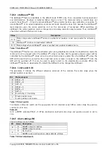
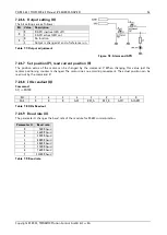
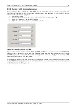
7.2.1.3
stallGuard
™
(G)
The stallGuard
™
feature is available in the default mode 0 (SPI) only. It is a sensorless load measurement
and stall-detection. Overload is indicated before steps are lost. The command letter
g
(small) does not
provide the setting (-7 … 7) but the actual stallGuard
™
value (motor load), so easy calibration is possible. To
use stallGuard™ in an actual application, some manual tests should be done first, because the stallGuard™
level depends upon the motor velocities and on the occurrence of resonances. When switching on
stallGuard, the motor operation mode is changed and microstep resolution may be worse. Thus, stallGuard™
should be switched off when not in use.
Value
Description
-7… -1
Motor stops when stallGuard
™
value is reached and position is set zero (useful for reference
run).
0
StallGuard™ function is deactivated (default)
1… 7 Motor stops when stallGuard
™
value is reached and position is
not
set zero.
Table 7.4: stallGuard
™
The stallGuard
™
function can also be activated when using step/direction mode. In step/direction mode the
motor will not be stopped when the stallGuard
™
value is reached, but the general purpose output will be
controlled by the stallGuard™ value: when the actual load value is greater than the stallGuard™ value, the
GPO will be switched on, and when the actual load value is lower or equal to the stallGuard™ limit, the
GPO will be switched off. This can be used to signal a stall to the step/direction controller. When the
stallGuard™ function is de-activated (0, default) the GPO will not be changed by stallGuard.
7.2.1.4
Limit switch (L)
The parameter ‘L’ defines the different reference entrances of the module. The motor stops when the
defined position is reached.
Bit
Motor stops at
0
REF_B = 0
1
REF_A = 0
2
GPI = 0
3
REF_B = 1
4
REF_A = 1
5
GPI = 1
6
0: soft stop, 1: hard stop
7
0: sets position zero
1: sets position not to zero
Table 7.5: Limit switch
To activate a reference switch set the appropriate bit to 1 (decimal entry). When motor stops the position
counter is set to zero.
Example:
AL 8
ENTER activates REF_B = 1. When destination reached motor stops and position counter is set to
zero.
7.2.1.5
Alert settings (N)
The bit settings are as follows:
Bit
Value Description
0
0
ALARM output is inactive
1
ALARM output is active
1
0
No function
1
ALARM is set to active when driver detects a failure
Table 7.6: Alert adjustments


