background image


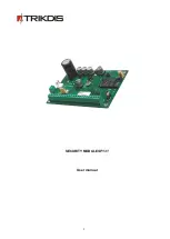
SECURITY MODULE 

SP131


User manual


Summary of Contents for SP131

Page 1: ...1 SECURITY MODULE SP131 User manual...

Page 2: ...12 CONNECTING TO A COMPUTER VIA GPRS 14 SPCONFIG SOFTWARE 15 SETTING THE MAIN CHARACTERISTICS OF SECURITY MODULE 15 USER CODE MANAGEMENT 17 INPUTS 18 SMS TEXT 19 PGM OUTPUTS 19 CMS REPORTING 20 USER...

Page 3: ...must conform to LST EN60950 standard safety requirements Security module is powered from 16 24V DC source or with 16 18V through a 2nd class power transformer from a 50 Hz frequency alternating curre...

Page 4: ...e g cash machine protection Multifunctional data bus MCI The module has a single wire Multifunctional data bus MCI which automatically recognizes and registers wired compatible devices maximum 4 Addit...

Page 5: ...tive and cost effective depends on cost of SMS console for security system control and management Trikdis SP131 Control has easy to use widget for Arming Disarming the system and checking the status o...

Page 6: ...must be powered from an independent source of energy e g solar power Power supply voltage is monitored If there is a problem with power supply it will be reported to central monitoring station and use...

Page 7: ...o up to 32 inputs with input expansion modules CZ8 Various expansion modules Up to 14 including keypads PGM terminals outputs 4 NO type terminals of the field effect transistor able to commutate up to...

Page 8: ...onnecting of iButton reader W131 and or transmitting module ZN1 ZN8 Terminals for connecting external circuits of the sensors Input ZN8 can be used for two wire fire detectors PGM1 PGM4 Programmable o...

Page 9: ...order to connect the external devices for example door and wall mounting tamper magnetic door contact fire sensors siren etc follow the schemes of this manual and wiring schemes of devices you want to...

Page 10: ...10 Wiring diagram Typical zone circuits Normally closed circuit NC Normally open circuit NO Normally open NO or normally closed circuit NC with end of line resistor EOL 2K2...

Page 11: ...ed to ZN8 input which must be set a as Fire zone b input target for two wire smoke detectors must be on Set IN8 as 2 Wire box must be checked in System Options System System option When needed a two w...

Page 12: ...zard instructions to finish the USB driver installation Note Computer has to have internet connection for proper USB driver installation 2 Start the program SPconfig 3 Choose the command Settings in t...

Page 13: ...13...

Page 14: ...setting an IP address xxx xxx xxx xxx external IP address of computer LAN yyyy forwarded port of IPcom program space Spaces are necessary in marked places the end mark of values Do not forget to end a...

Page 15: ...hange them only then there is a need and knowledge that they mean Setting the main characteristics of security module In the System Options directory of SPconfig the common parameters of the module ca...

Page 16: ...16...

Page 17: ...em User number Section for entering name of the user The name of the user will be included in SMS message Section for entering user telephone number which will be allowed to ARM DISARM the security sy...

Page 18: ...ting parameters of the necessary input 1 Enable Alarm reporting Enable Restore reporting Marked zone can be bypassed The module will not react to disturbances in a protected zone if their duration wil...

Page 19: ...ts directory PGM outputs PGM outputs parameters are configured in Outputs directory Every output mode is described in annex Note If there is PGM output set to Remote Control by DIAL mode Remote Arm Di...

Page 20: ...reporting to central monitoring station parameters of the module can be set in CMS Reporting directory The exact values of parameters should be provided by a person in charge of the central monitoring...

Page 21: ...n User Reporting directory Note CMS reporting has priority over User reporting Messages are sent to monitoring station first and only then to the user If there is a need for messages to be sent only t...

Page 22: ...dules The Bus modules directory presents the list of expansion modules connected to YEL GRN data bus and registered on SP131 module for example keypad or input expanders MCI Bus Modules The MCI Bus Mo...

Page 23: ...F6 button to write parameters into memory of module Firmware upgrade If there is a new update firmware of SP131 module can be updated 1 Download the latest version of the configuration program SPconf...

Page 24: ...state will be changed to opposite if N output is set to Remote Control by SMS N values 1 2 3 4 PSW000000 5N 0 Nth output state will be changed to OFF if N output is set to Remote Control by SMS N valu...

Page 25: ...is a violation of Delay zone a time Entry Delay count will start for entering premises and User code 3 ARM in SLEEP mode Note If there is zone alarm other than Interior STAY or Instant STAY zone secu...

Page 26: ...be illuminated on a keypad according to serial numbers of already entered user codes Enter a 2 digit serial number of User code for example 02 and then enter the new 4 digit User code twice Touch the...

Page 27: ...ENTER Enter the user code and do not violate Delay zone for example do not open the door If there is no Delay zone violation during Exit Delay time the security panel will arm in STAY mode Keypad keys...

Page 28: ...ult 1234 The key will start to flash and illuminated keypad numbers will display serial numbers of already entered user codes Enter a 2 digit serial number of User code you want to delete for example...

Page 29: ...will be sent Break of input circuits is allowed during the time periods for entering or leaving the premises Entry Delay and Exit Delay Set by default on ZN2 EOL Interior STAY Operates similarly to I...

Page 30: ...l System State Output for connecting a light emitting indicator During ARM mode the continuous signal is formed and during the time for leaving entering the premises Entry Delay Exit Delay pulse signa...

Page 31: ...ng a state indicator During alarm the continuous signal is formed Lost Primary Channel A continuous signal is formed if the primary communication channel is lost Lost Secondary Channel A continuous si...

Page 32: ...nd relevant electronic and technical conditions Manufacturer is in no way associated with GSM GPRS Internet service providers operators thus UAB TRIKDIS is in no way responsible for any defects in Dev...

Reviews: