OPERATOR'S MANUAL
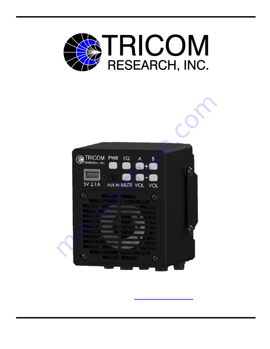
TCR-SPK-DUALv2
AMPLIFIED DUAL-NET SPEAKER
DOCUMENT # 90400-01480
Tricom Research, Inc.
•
www.tricomresearch.com
17791 Sky Park Circle, Suite J, Irvine, CA 92614
Phone: (949) 250-6024 Fax: (949) 250-6023
Page 1: ...ERATOR S MANUAL TCR SPK DUALv2 AMPLIFIED DUAL NET SPEAKER DOCUMENT 90400 01480 Tricom Research Inc www tricomresearch com 17791 Sky Park Circle Suite J Irvine CA 92614 Phone 949 250 6024 Fax 949 250 6023 ...
Page 2: ...N DESCRIPTION DATE A INITIAL RELEASE 12 SEPTEMBER 2020 B UPDATED TABLE 1 2 WITH 5 VDC MIC BIAS 15 MARCH 2022 C UPDATED APPLICABLE SECTIONS TO REFLECT CONNECTOR CHANGE 16 AUGUST 2022 Note The latest version of this manual can be downloaded from our website at www tricomresearch com ...
Page 3: ...r Use 7 3 2 Mounting Provisions 7 3 3 DC Input Power 9 3 4 Radio Interfaces 10 3 5 Handset Interfaces 10 3 6 Firmware Updates 10 3 7 Optional Slave Speaker 10 LIST OF TABLES Table 1 1 General Specifications 3 Table 1 2 Interconnect Characteristics 4 Table 2 1 Front Panel Controls 5 Table 3 1 DC Input Power Connector Pinout 9 LIST OF FIGURES Figure 1 1 TCR SPK DUALv2 Amplified Dual Net Speaker 1 Fi...
Page 4: ...wer audio amplifier Dual Digital Signal Processors DSP for superior audio performance Selectable EQ settings ensure quality sound in various environments Simplified front panel compact and low profile Individual net volume controls with rapid mute function Mute and missed traffic LED indicators for each net Dimmable NVG compatible LEDs Compatible with existing communications equipment Local handse...
Page 5: ...D GLOSSARY AGC Automatic Gain Control CONN Connector dB Decibel GND Ground HDST Handset Hz Hertz I O Input Output kHz Kilohertz LED Light Emitting Diode PTT Push to Talk RX Receive VDC Volts Direct Current W Watt TX Transmit ...
Page 6: ...NS Note Information in Table 1 1 is included for reference only and does not constitute a warranty of performance Table 1 1 General Specifications DC Input 12 32 VDC Audio Input Standard Tactical Radio Audio Audio Frequency Response Radio 300 3 000 Hz Aux 125 20 000 Hz Distortion 2 at Full Power Speaker TX Mute Automatic with PTT Volume Controls Net A Net A Net B Net B each with audio confirmation...
Page 7: ...o B Handset Mic to Radio B Pins 9 10 11 Not Connected Pin 12 Shield Wire RADIO A Radio A Hirose HR30 6R 6S 71 Pin 1 GND Pin 2 RX Audio A Pin 3 PTT A Pin 4 TX Audio A Pin 5 Microphone Bias from Radio A Pin 6 Shield Wire HDST B AUX A B Handset s Hirose HR30 7R 12P 31 Pin 1 GND Pin 2 RX Audio A Audio from Radio A Pin 3 PTT A Pin 4 TX Audio A Handset Mic to Radio A Pin 5 5 VDC Microphone Bias Pin 6 RX...
Page 8: ...ready for operation Net A and Net B volume is adjusted using the A A and B B pushbuttons The radio volume control controls handset volume Set Up is complete once the unit is powered on and proper volume levels set NOTE A minimum radio volume level equivalent to that which can be heard on the standard handset is required for proper operation of the speaker s auto noise gating and AGC functions Ensu...
Page 9: ...s of the A button increases volume in ten steps audio logarithmic taper with each increase indicated by a single short tone A single long tone indicates maximum volume has been selected Holding the A button increases volume through the steps continuously The A button is backlit green anytime Net A is muted The A button will flash when Net A is muted and radio traffic is detected alerting the user ...
Page 10: ...le handset cables HDST A and HDST B are used the handset connected to HDST A will only control Radio A and the handset connected to HDST B will only control Radio B If dual handset cables MAIN A B and AUX A B are used the MAIN A and AUX A handsets control Radio A and the MAIN B and AUX B handsets control Radio B 3 0 INSTALLATION 3 1 PREPARATION FOR USE After unpacking the system and inspecting for...
Page 11: ...8 Figure 3 1 TCR SPK DUALv2 Outline Drawing w Mount Figure 3 2 TCR SPK DUALv2 Outline Drawing w o Mount ...
Page 12: ...e reverse polarity protection including protection from connecting the positive voltage input to Pin B GND with a grounded chassis Figure 3 3 DC Input Power Connector HR30 6R 6P 71 Table 3 1 DC Input Power Connector Pinout Pin I O Description 1 I 12 32 VDC 2 I Electrical Ground GND 3 O Optional Slave Speaker 4 O Optional Slave Speaker 5 I O Spare 6 Not Connected Figure 3 4 DC Power Cable 120 Part ...
Page 13: ...ias exists on the HDST A MAIN A B and HDST B AUX A B connectors as described in Table 1 2 This microphone bias is passed through the external MAIN A B and AUX A B cables to pin F on the 6 pin audio connector When the speaker is powered off the microphone bias provided by the radio is passed through the TCR SPK DUALv2 to Pin F on the 6 pin audio connector 3 6 FIRMWARE UPDATES The TCR SPK DUALv2 fir...