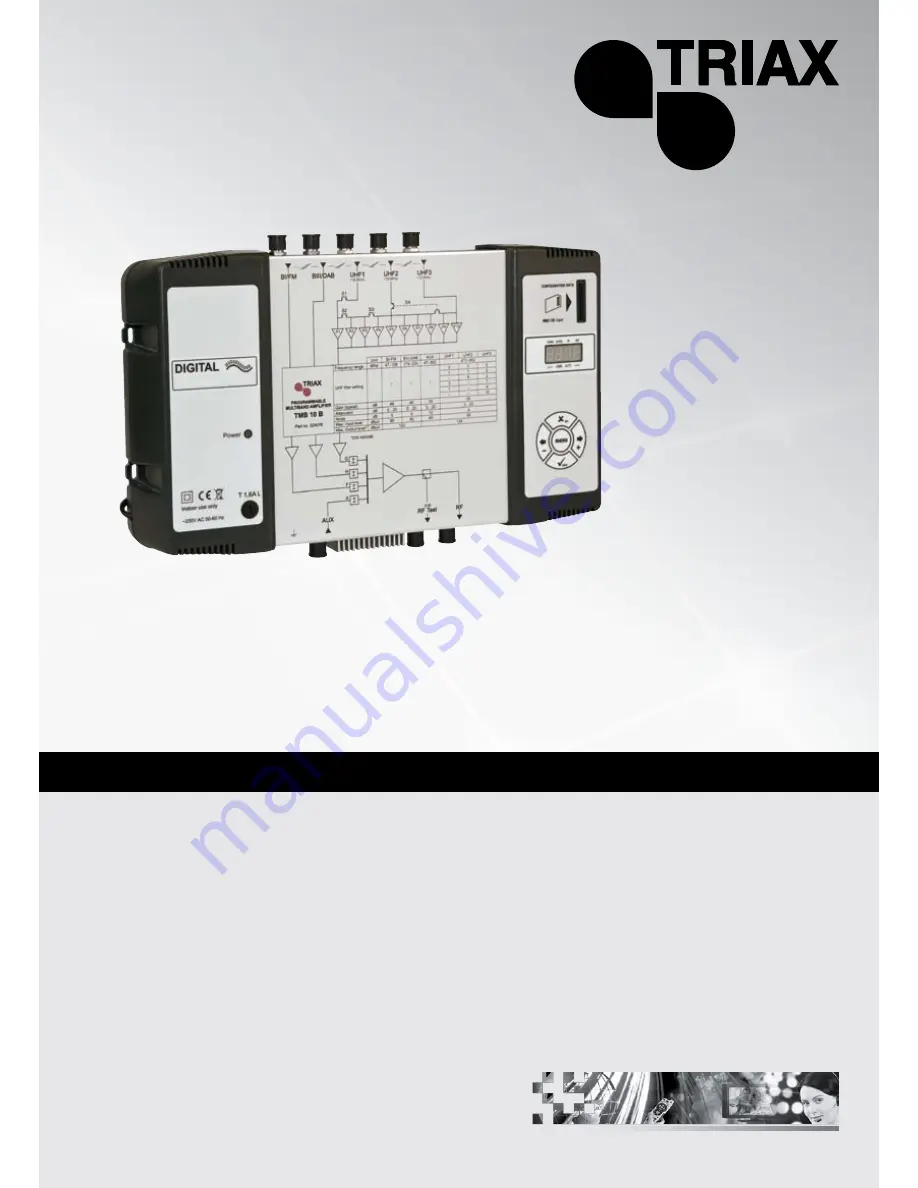
Programmable Multiband Amplifier
TMB 10A Ref.: 324575
TMB 10B Ref.: 324576
TMB 10C Ref.: 324578
TMB 10S Ref.: 324577
Mounting instruction
GB |
TRIAX - your ultimate connection
Page 1: ...Programmable Multiband Amplifier TMB 10A Ref 324575 TMB 10B Ref 324576 TMB 10C Ref 324578 TMB 10S Ref 324577 Mounting instruction GB TRIAX your ultimate connection ...
Page 2: ...b b bu u ut tti iio o on n n o o of ff U U UH H HF F F f ffi iil llt tte e er r rs s s 7 U U UH H HF F F f ffi iil llt tte e er r r w w wi iid d dt tth h h C C CH H HA A AN N N m m me e en n nu u u 9 F F Fi iin n ne e e t ttu u un n ni iin n ng g g 10 C C Co o on n nf ffi iig g gu u ur r ri iin n ng g g t tth h he e e a a at ttt tte e en n nu u ua a at tto o or r rs s s L L LE E EV V VE E EL L L m...
Page 3: ...y band and automatic control of the UHF output level for aligning service plan levels TMB 10A Ref 324575 5 inputs BI FM BIII DAB AUX UHF1 UHF2 UHF Gain 55 dB BI BIII Gain 48 dB AUX Gain 39 dB UHF output level 124 dBµV DIN 45004B TMB 10B Ref 324576 6 inputs BI FM BIII DAB AUX UHF1 UHF2 UHF3 UHF Gain 55 dB BI BIII Gain 48 dB AUX Gain 39 dB UHF output level 124 dBµV DIN 45004B TMB 10C Ref 324578 6 in...
Page 4: ...there are traces of condensation on the unit do not use it until it has dried completely The mains power cable and the HF connection cables must be in good condition and free to move neither crushed nor obstructed The mains plug easily accessible for the technician must be out of reach of children Earthing the unit Your aerial installation must comply with the requirements specified by the Europea...
Page 5: ...cable C Co on nn ne ec ct ti in ng g t th he e u un ni it t Note UHF inputs are remotely supplied and protected against short circuits The power available is 12 or 24V 50mA max The preamplifier is detected automatically only the remote power voltage can be programmed Max Output level Max Input level Noise Attenuator Gain typical UHF filter setting Frequency range MHz Unit dBµV dBµV dB dB dB 47 108...
Page 6: ...ert to factory settings follow the procedure below 1 Disconnect the power cable 2 Press the esc button and hold it 3 Connect the power cable The unit erases all the programming parameters including the PIN code and switches to standby mode You can release the esc button when the display shows 8888 D Da at te e o of f m ma an nu uf fa ac ct tu ur re e If necessary to consult the unit s date of manu...
Page 7: ...To exit a menu press the menu button Note If the button is not pressed for one minute the unit switches to standby mode M M Me e en n nu u us s s CHAN Configuration of UHF filters Channel Bandwidth 1 to 7 channels 8 to 56 MHz LEVEL Configuring of attenuators IN Configuration of filter distribution on UHF1 2 and 3 inputs Selection of remote power supply 12 or 24 VDC AUTO Use of the AGC Automatic al...
Page 8: ...of 8 to 56 MHz 1 to 7 channels D D Di i is s st t tr r ri i ib b bu u ut t ti i io o on n n o o of f f U U UH H HF F F f f fi i il l lt t te e er r rs s s Go to the menu IN by placing the light segment under the IN mark and press enter Press enter again to change the configuration of the UHF inputs part of the display flashes Press the buttons or to select the distribution of the filters over the ...
Page 9: ...X esc 0 0 or Select the distribution of UHF filters enter 0 0 or Remote power supply enter X esc This menu is used to select the value of the remote power supply on the inputs UHF 1 2 and 3 The unit automatically detects the amplifier connected and switches the remote power supply to ON Distribution of UHF filters 352 172 082 307 109 001 Remove the mains cable before any wiring work GB 9 ...
Page 10: ...X esc X esc Select the filter to configure 0 0 or Choose the start channel Choose the end channel 0 21 1 channel max 7 channels CHAN menu Filter start channel If the filter is not used the display shows Filter number 1 to 10 0 for filter no 10 The display dot flashes when the filter has a width 1 channel C Channel menu TMB Programmable Multiband Amplifier TMB 10A TMB 10B TMB 10C TMB 10S GB 10 ...
Page 11: ...filter concerned to adjust the filters according to the characteristics of the signals received offset adjacent channels etc Check the offset on your measurement apparatus Start enter X esc 0 0 The function only acts on the filter selected Select the filter using the keys and enter enter X esc X esc GB 11 ...
Page 12: ... u u Go to the LEVEL menu by placing the light segment under the LEVEL mark and press enter Press the buttons or to select the channel to configure Confirm by pressing enter When the display flashes you can configure the attenuation 20 indicates attenuation 0 1 indicates max attenuation Confirm by pressing enter X esc Start menu enter 0 0 or enter Select sub menu L level menu Attenuation 1 to 20 d...
Page 13: ...tart menu enter enter AUTO menu enter 0 0 or enter Display the value of the output level X esc X esc min max 0 0 or Select the sub menu enter enter 0 0 or enter X esc X esc IMPORTANT The unit memorizes the average output level A variation of 1 dB triggers the function and compensates the variation within gain and attenuation limits AGC mode hides all other menus To modify the parameters switch the...
Page 14: ...ing starts the display shows Good when the procedure is complete PIN activation and configuration of the PIN code When this function is active the PIN code is requested to access the menus display your PIN code using the keypad and confirm by pressing enter If no key is pressed for 30 seconds the unit switches to standby mode and the PIN code must be entered again to access the menus Important Whe...
Page 15: ...InP read configuration files PIN activation and configuration of the PIN code The SD MMC card must be formatted in FAT 16 The files should be placed in the root directory If the SD MMC card has no configuration file the display will show noFL during reboot Select the sub menu GB 15 ...
Page 16: ...Continued from the previous page TMB Programmable Multiband Amplifier TMB 10A TMB 10B TMB 10C TMB 10S GB 16 ...
Page 17: ... Start Insert the SD card The dot flashes when the process begins When the display flashes the file has been created on the SD card Press enter to confirm and overwrite the existing file Select the file to read GB 17 ...
Page 18: ...InP Import Menu Start Insert the SD card Select the file to read The dot flashes when the process begins TMB Programmable Multiband Amplifier TMB 10A TMB 10B TMB 10C TMB 10S GB 18 ...
Page 19: ...ply of the LNB OFF 13 17 VDC to activate the 22kHz generator and the 9dB equalizer Start menu enter 0 0 or enter Select the channel to configure SAT menu 0 0 or enter 0 0 or Select the sub menu enter Display the value X esc X esc X esc IL adjust the output level Po LNB supply 0 13 or 17V DC to 22kHz generator on off E equalizer on off GB 19 ...
Page 20: ...nuator Gain typical UHF filter setting Frequency range MHz Unit dBµV dBµV dB dB dB 47 108 BI FM 122 80 5 0 20 48 174 230 BIII DAB 80 5 0 20 48 47 862 AUX 80 10 0 20 39 124 80 9 0 20 55 UHF1 1 4 470 862 UHF2 5 3 2 3 6 DIN 45004B TMB Programmable Multiband Amplifier TMB 10A TMB 10B TMB 10C TMB 10S GB 20 ...
Page 21: ... Attenuator Gain typical UHF filter setting Frequency range MHz Unit dBµV dBµV dB dB dB 47 108 BI FM 122 80 5 0 20 48 174 230 BIII DAB 80 5 0 20 48 47 862 AUX 80 10 0 20 39 UHF1 124 1 3 1 3 470 862 UHF2 80 9 0 20 55 8 7 5 UHF3 10 9 7 2 2 2 DIN 45004B GB 21 ...
Page 22: ...Diagram TMB 10C DIN45004B TMB Programmable Multiband Amplifier TMB 10A TMB 10B TMB 10C TMB 10S GB 22 ...
Page 23: ...ain typical UHF filter setting Frequency range MHz Unit dBµV dBµV dB dB dB 47 108 BI FM 116 80 5 0 20 43 174 230 BIII DAB 80 5 0 20 43 47 862 AUX 80 10 0 20 33 UHF1 120 1 3 1 3 470 862 UHF2 80 9 0 20 48 8 7 5 UHF3 10 9 7 2 2 2 950 2150 SAT 79 6 0 20 40 DIN 45004B GB 23 ...
Page 24: ...F output attenuator dB 0 to 20 UHF output adjustment by AGC dB 9 to 10 Max Output level VHF UHF SAT DIN45004B dBµV 122 124 116 120 120 Test output dB 20 FILTERING Distribution of filters See page 8 of this manual Width of filtering channels MHz 8 to 56 selectivity of filters at 16MHz dB 16 Adaptation of inputs dB 10 Adaptation of outputs dB 10 POWER SUPPLY Voltage VAC 230 Power consumption at 230V...
Page 25: ...5 6 M H z F ilte r 4 1 to 7 c h a n n e ls 8 to 5 6 M H z F ilte r 5 1 to 7 c h a n n e ls 8 to 5 6 M H z F ilte r 6 1 to 7 c h a n n e ls 8 to 5 6 M H z F ilte r 7 1 to 7 c h a n n e ls 8 to 5 6 M H z F ilte r 8 1 to 7 c h a n n e ls 8 to 5 6 M H z F ilte r 9 1 to 7 c h a n n e ls 8 to 5 6 M H z F ilte r 1 0 1 to 7 c h a n n e ls 8 to 5 6 M H z L e v e ls U H F 1 1 o r 3 filte rs U H F 2 5 7 o r ...