background image

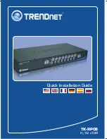
TK-RP08

H/W: v1.0R

Quick Installation Guide

Summary of Contents for TK-RP08

Page 1: ...TK RP08 H W v1 0R Quick Installation Guide ...

Page 2: ...Table of Contents English Troubleshooting 1 1 2 5 7 1 Before You Start 2 How to Install 3 Operation and Configuration Table of Contents Version 04 10 2008 ...

Page 3: ...k Mount Brackets Power Cord RJ 45 Ethernet Cables AC powered Device Windows 98SE 2000 XP Vista PC required TK IP101 Optional Broadband DSL Router e g TW100 S4W1CA Optional Remote Power Controller TK RP08 Servers Day Night Internet Camera Server with 2 Way Audio TV IP312 2 Bay SATA I II Network Storage Enclosure 3 5 drive TS S402 1 Port KVM Switch over IP TK IP101 ...

Page 4: ...o the TK RP08 and then to a power outlet 2 How to Install English 2 Standalone 2 Connect the RS 232 cable from a serial port on your computer to the serial port on the TK RP08 3 Connect your AC powered device to one of the eight power outlets on TK RP08 ...

Page 5: ...ble to the Daisy Chain Output port on the second KVM switch Then connect the opposite end of the RJ 45 Ethernet cable to the Daisy Chain Input port on the third slave TK RP08 Repeat for each additional TK RP08 Note You can daisy chain up to 16 TK RP08 together with a maximum of 128 AC powered devices 1 Connect one end of the provided RJ 45 Ethernet cable to the Daisy Chain Output port on the first...

Page 6: ...et Note If you would like to mount the KVM switch to a EIA 19 equipment rack install the included mounting brackets to the sides of the KVM switch secure them with the screws provided and then mount the KVM switch to the equipment rack with the hardware provided by the equipment rack manufacturer 1 Attach the mounting brackets to both sides of the KVM switch and secure them with the provided screw...

Page 7: ... on it for 2 seconds Bank Number Indicates the sequence of the KVM switch when daisy chained ALARM When this LED is solid red the power outlet is not working properly When this LED is off the power outlet is working fine When this LED is flashing red timer scheduled is enabled for that port or firmware is being upgraded ON When this LED is green the power outlet is powered on When this LED is off ...

Page 8: ...le click the TRENDnet IP Power Manager icon on your desktop 2 Follow the InstallShield Wizard instructions and then click Finish 4 Click on Setting and then click Connect 5 Click OK 7 Click OK 6 Click the power button ...

Page 9: ...l port on the computer Third connect to a different computer The Alarm LED is red What should I do First turn off and disconnect the device attached to the corresponding power outlet Press the power button to the corresponding power outlet several times Second press on the reset button on the back The Current LED is flashing What should I do The maximum allowable current load 15 amps has been exce...

Page 10: ...CATIONS COULD VOID THE USER S AUTHORITY TO OPERATE THE EQUIPMENT Waste electrical and electronic products must not be disposed of with household waste Please recycle where facilities exist Check with you Local AuthorityorRetailerforrecyclingadvice ADVERTENCIA En todos nuestros equipos se mencionan claramente las caracteristicas del adaptador de alimentacón necesario para su funcionamiento El uso d...

Page 11: ...register your product online Go to TRENDnet s website at http www trendnet com register TRENDnet Technical Support US Canada 24 7 Tech Support Toll Free Telephone 1 866 845 3673 Europe Germany France Italy Spain Switzerland UK English Espanol 24 7 English Espanol 24 7 Worldwide Telephone 31 0 20 504 05 35 Toll Free Telephone 00800 60 76 76 67 ...

Reviews: