N-Platform Hardware Installation and Safety Guide
41
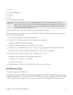
2.
Latch
3.
Latch Locking Screw
4.
Handle
5.
Fan
6.
Power Input Terminal Block
Caution:
Do
not
attach a ground wire to the ground screw on the DC power supply module. The
ground wire must be attached to the N-Platform chassis ground terminal with a #10 screw.
The ground terminal is located in the rear of the N-Platform chassis. Refer to the chassis
diagram for your N-Platform model.
The Status LED is green when the module is powered and running normally.
When the DC power supply has been securely placed in the device, use the following procedure to connect
power to the DC power supply:
1.
Locate the ground screw on the back of the chassis.
2.
Attach a 12 or 14 AWG ground wire to the chassis #10 ground screw.
The wire should be crimped with a ring lug.
3.
Locate power input terminal block on the back of the module.
4.
Attach the 12 or 14 AWG DC power wires to the power input terminal block labeled -48V and RTN.
The power wires should be crimped with lug spades to ensure a secure connection.
5.
Connect the other side of the power cable to the SELV power source.
The power source should meet the following requirements:
• Voltage: -36 to -60 Vdc +/- 20% SELV
• Current: 8/4 Amps
6.
When ready, power on the device with the button on the front of the chassis.
N-Platform fans
Provides fan replacement information.
In normal operation, the N-Platform fan is not hot-swappable. If you need a replacement fan, contact your
TippingPoint representative to order an IPS N-Platform Spare Fan unit (part number TPNN0080). The IPS
N-Platform Spare Fan is a replacement unit and can only be used with TippingPoint N-Platform devices.

